| Mechanics | ||
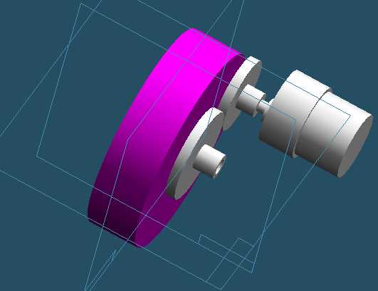
 SolidEdge CAD model of Wilt We had several ideas in mind for the drivetrain. First, we considered directly mounting wheels to our motor shafts. After looking at the roaches, however, we decided that it was difficult to keep the wheels exactly perpendicular to the ground if we couldn't find motor shafts that were greater than the width of the wheels. Additionally, without a long motor shaft, we would be side-loading the motor's shaft with a substantial amount of weight which would slow it down and cause premature wear. So we decided to do an indirect drivetrain by mounting freely spinning wheels to the base and connecting a motor to drive it in some fashion. We chose 4" razor wheels (including ball bearings) from Walmart. While these wheels worked fine, we would probably have chosen some non-Walmart variety given the enormous imperfections in the wheels we had -- there were large flat spots on both wheels. However, the platform rolled very nicely on the ball bearings, and the price was right since we knew we might mess up the mounting and have to buy more. We also chose to drive our motor with a Hsiang-neng GH35GM series motor. Given that the nearby Jameco company sells a wide range of these motors (huge range of options of speed/torque), and that all of the motors have identical shafts and mounting holes, by designing around these motors we could easily change the motor if needed without re-designing the rest of our drivetrain. These motors have a shaft diameter of .24 and a length of .7 -- both excellent for mounting small wheels, gears, pulleys or sprockets. To drive the wheels with a motor, we considered three different systems:
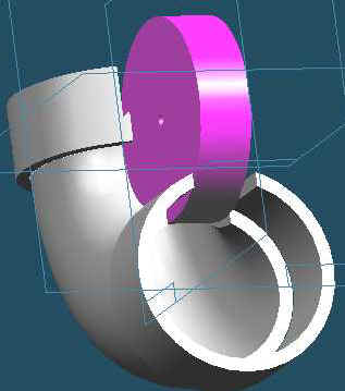
We realized each of these techniques had some serious downfalls. For friction drive, it would be difficult to keep the two wheels in enough compression to move consistently. Plus, the razor wheels were very slick and it would be hard for another wheel to get enough friction to cause motion. The belt and chain drive seemed like our best option because the alignment didn't have to be perfect. However, it would be difficult to attach a sprocket to our razor wheels, and every pulley/belt & sprocket/pulley system we could find were very expensive. If we were to break a chain or belt it would be expensive, difficult, and time-consuming to find a replacement. We realized that implementing gearing would be difficult because the tolerances would have to be very close -- if the teeth didn't mesh, the system would be unusable. Also, procuring gears seemed like it would be very expensive -- gears in Jameco and other catalogs were extraordinarily expensive and didn't exactly fit the shafts of our wheels or motors. Fortunately, a trip to Triangle Machinery in San Jose with our motors and wheels in hand helped us formulate our solutions. They have an incredible selection of gears, some larger sprocket/chain components, and a limited amount of belt/pulley systems. By digging through the bins of loose gears, we assembled five or six viable gearing options -- an entire family of plastic gears with the right size bores, and an entire family of metal gears that would also work. We chose to start with the plastic gear family because they had larger teeth and that meant our mounting could be a lot less precise with no slippage. So, we mocked up the drive system in SolidEdge:
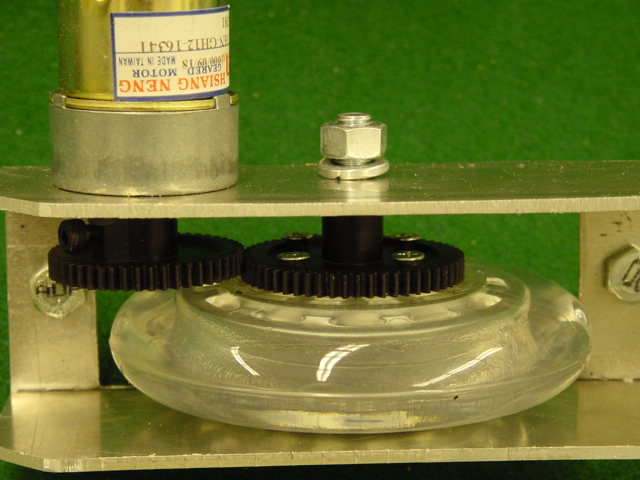
Now it was easy to create a sheet metal bracket to hold this system together. Using the SolidEdge sheet metal system and importing the drivetrain assembly (above) as a construction element, it was easy to design the U-shaped brackets. After flattening the brackets and printing them, we taped them to a .100-inch thick aluminum sheet (in retrospect, it was a tad too thick, perhaps .06 or .08 would have been a little more reasonable and easier to work with). After long hours in the machine shop at the band-saw, drill press, punches, and benders, we had two brackets, which when fully assembled, looked like this:
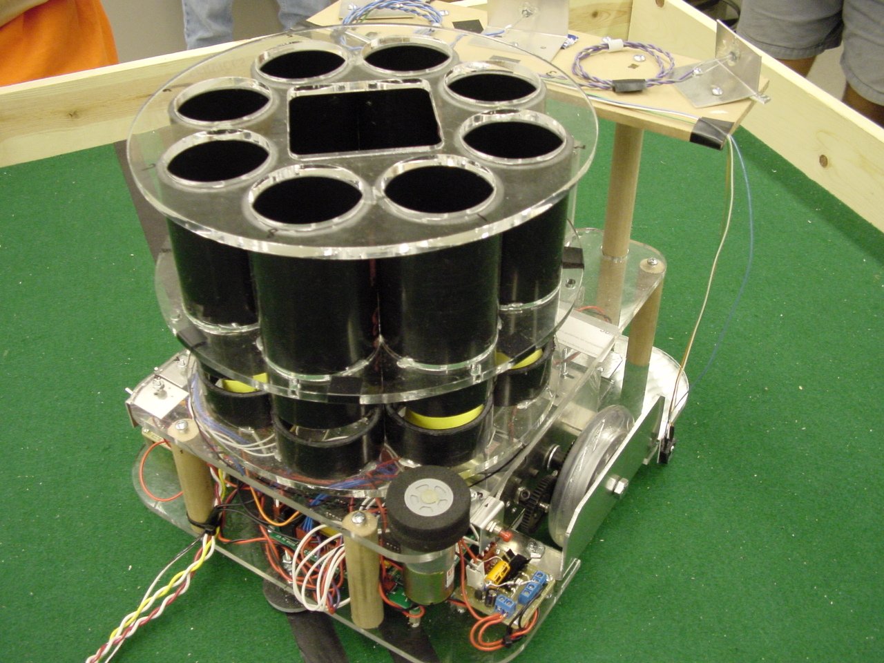
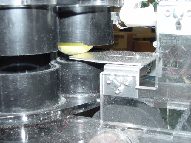
As you can see, the pinion is attached to the motor with a set screw. The large gear is easily attached to the wheel with four screws. The main axle is just a 5/16 hex bolt. This turned out to be a great drive system. They are really strong, and they eliminate sideloads on the motor. One of our brackets was slightly mis-aligned (probably a slip up with the drill press) but a little last-minute shimming solved the problem. In retrospect, the motors we chose did not have enough torque. In the days before the competition would have gladly traded some of our top-end speed for more torque. Yes, we could have easily swapped out our motor for one with more torque like we had provisioned for, but alas Jameco was not open on Sunday, and by Monday it would have been too late to make the change and update our software in time for the competition. We chose to load the Nerf ‘basketballs’ into our launcher by way of an 8-column carousel. The carousel holds four balls in each column and rotates between rounds by way of a friction-drive system. The drive system uses a high-torque motor to spin the carousel, which is attached to a non-moving platform (dubbed ‘The Falcon’ on account of its eventual resemblance to the Millennium Falcon spacecraft from the Star Wars movies) via a lazy-susan bearing. Beneath the carousel is a hole in the falcon that allows balls to be dispensed whenever a column rotates to the position directly above the hole. As the carousel turns, a stationary ledge passes through the slots cut at the same height into each column. The height of the ledge is selected so that it will separate the bottom-most ball from the ones above it. Thus, when the bottom ball is released, those above it will continue to be supported by the ledge and will not fall. Meanwhile a pair of IR sensors, mounted with only a narrow gap between them, straddle an encoder ring on the carousel and are used to monitor its rotational position at all times. Before detailing the construction of this system, a couple points on why we selected this method for our loader: Alternatives – Before pursuing the carousel loader for our final implementation, we considered several other mechanisms such as:
While each alternative had its own merits and drawbacks, we were able to analyze the collection as a whole and in so doing assess which characteristics of the loader were most important. Those characteristics were:
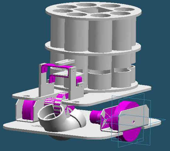
In rating all of our options against these metrics, it became obvious that the carousel provided the best combination of performance in these areas. For instance, the carousel easily serializes the balls using pipe columns, without having the difficulty of bending a pipe or arranging a series of ramps so as to allow them to roll smoothly. Further, by using our ledge mechanism to separate the current ball from those still in waiting, we could achieve excellent granularity without the complexity of moving parts, the need to drive a solenoid for the purpose of gating, or the unreliable feeding of a hopper. Lastly, be leveraging gravity as our force for deploying the current ball, we could save ourselves the power needed to drive a large screw or other conveyance mechanism. Between cycles, the entire carousel could be rotated, which is a motion easily obtained using low-speed DC or stepper motors. Carousel Construction Capacity: Without much regard for the feasibility of actually launching a large number of balls in only two minutes, we chose to maximize our utilization of the ‘1 cubic foot’ volumetric robot requirement. This meant a selection of 8 columns, each 4-balls tall, for a grand total of 31 balls (the loading location is always empty to begin with). By arranging the pipes in tight circle (roughly 9” in diameter) and accounting for the height required by the pipe launcher and motors beneath the carousel (about 3.5”), we were able to successfully store 31 balls without violating the robot size limitations. Faceplates: However, to ensure this qualification given the tight requirements, we needed to machine the carousel to fairly accurate tolerances. Thus, we employed Solid Edge and the LaserCam to design acrylic top and bottom faceplates between which the pipe columns would be secured. The faceplates to provide stability and alignment since the pipes are to be affixed directly atop and beneath them using hot melt. Pipes: We then cut eight pieces of 2" ABS to the same 6" height using the stock sheet metal band saw. We found it difficult to make the cuts in the pipe flush to the ends and of the same length each time, yet this was crucial to the fit of the faceplates. With careful machining we were able to overcome this dilemma and produce eight nearly identical pipe columns. Slotted Pipe: Next, we
used the mill and a rectangular head to slot each pipe at the same
height. The height is
chosen to ensure the ledge will have room to be adjusted such that it
always falls between the last two balls in the queue.
The mill proved an invaluable means for replicating and measuring
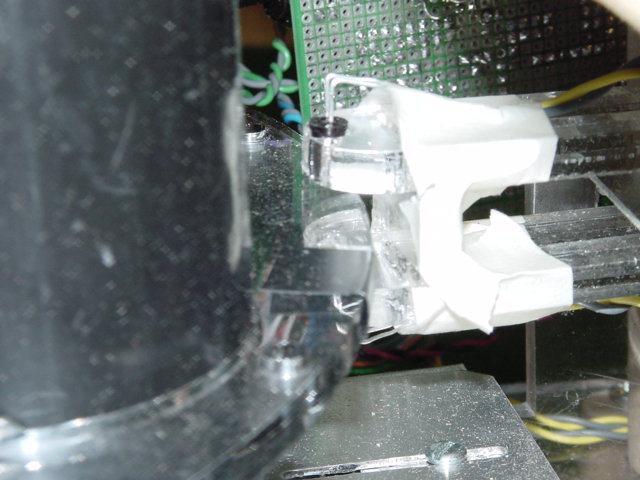
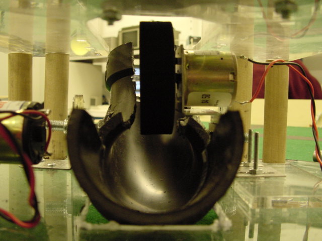
the depth of ledge slot in each of the eight pipes. Encoder Ring: To accurately control the position of the carousel, we need a way to sense its location at all times. In order to support this closed-loop feedback, we employed IR sensors and affixed a matching ring in the middle of the carousel. The ring not only provided position information, since we placed a piece of electrical tape at the position on the ring corresponding to the middle of each column, but it also served to hold the columns in place firmly, which proved vital during the assembly process. (see picture of encoder ring / IR detector-emitter pair at right) Encoder Sensors: The pair of IR sensors used in the encoding scheme was directly aligned with only a 0.30” separation. They were held in place using a custom acrylic pair of arms that was attached to another aluminum bracket, identical to that used to support the ledge (see above). Then, using the screw slots in the arms to adjust depth relative to the column’s encoder ring, and tweaking the bracket to control the height relative to the ring, the sensors were placed such that they straddled the encoder ring. Since acrylic is transparent to IR, the sensors would continuously receive signal until one of the pieces of opaque black tape on the ring passed between them. With only 0.05” of play in the gap between the encoder ring (made of 0.25” acrylic) and the sensors, it was critical that we exploit the flexibility we designed into the mounting hardware to tune the system accurately. Ledge:
We constructed the ledge out of 0.05’’ aluminum selected for it
rigidity, so that it would withstand the impact of the rotating ball
columns, and its easy-of-use. After shearing, punching, and drilling out this piece, we
secured it with a specially-made bracket that we had also formed from
aluminum. The design of the
ledge and its mounting was focused on flexibility so that the system
could be easily tuned once assembled. So, while a large screw slot
controlled the position of the ledge relative to the depth of the
columns, the bracket on which it was mounted used a similar screw slot
technique to adjust the height of the ledge relative to the slots in the
columns. Lazy Susan Bearing: The entire carousel, except for the stationary accessories such as the ledge and IR sensors, was screwed onto a 3” lazy-susan bearing. By using SolidEdge to align the screw holes in the bearing with those we drilled in both the carousel and the falcon, the mounting was straightforward. The lazy-susan was an excellent choice of bearing for rotating the carousel since it provided little friction or slop that could otherwise have interfered with our friction drive system and positioning. Friction Drive Motor: We chose the Hsiang-Neng GH12-1921Y, a 12V, 42-rpm gearhead DC motor with 8 Kg/cm of stall torque and a 132:1 gear ratio to drive the carousel. Since the carousel did not have to move particularly fast, but because its size and the weight of its contents, in addition to any friction that we could encounter if the ball columns were to somehow bind while rotating on the surface of the falcon, required a large torque, we selected a heavily geared motor. With 150 mA of no-load current, even the torque of the motor in the unloaded case is strong compare to our other motors on the robot. We attached the motor to the falcon using holes we had included in our SolidEdge and drilled out on the LaserCam. This proved much safer than using the drill press. Friction Drive Wheel: We then selected a small foam rubber wheel that we attached to the motor shaft using simple hot melt. Our original mechanism for securing the motor shaft was a piece of model airplane fuel tubing whose inner diameter matched that of the motor shaft and whose outer diameter fit the bore of the wheel. Though adequate for prototyping, this approach had a tendency to fail after repeated usage, as the wheel would slowly walk off the shaft. Once secured with hot melt, though, the wheel performed exactly as expected. We had chosen a foam wheel since it could be easily compressed to provide the necessary contact force and maintain friction with the carousel and not slip.Our ball launcher is essentially modeled after a pitching machine whereby the ball is accelerated from the force applied tangentially by a high-speed wheel in its path. In our case, a single foam wheel is mounted above a L-shaped elbow of ABS pipe. The wheel is depressed far enough into the groove of the elbow that, when a ball is loaded, it is squeezed between the wheel and the pipe, then accelerated out in the direction dictated by the remaining section of pipe (the muzzle). Pipe Elbow: While the lateral direction of the ball’s flight is governed by the muzzle and the heading of the robot, the vertical direction is a function of the wheel speed, wheel depth into the elbow, and the angle at which the elbow sits in its mounts. Thus, it is important the pipe elbow be secured in a manner that is both robust and adjustable. To that end, we used epoxy to affix two bolts to the exterior of the pipe, one on either side, and then constructed aluminum brackets to receive the bolts. This allowed us to fasten the pipe securely, while also providing the freedom to rotate the orientation at which it was sitting in the mounts. However, had we been more clever in aligning the bolts while securing them, we may have been able to achieve a more level axis, keeping them parallel to the base of the robot under aligned conditions. Instead, we compensated for that slope by introducing asymmetries into the mounting brackets. Additionally, we constructed an adjustable bracket to hold the throwing motor so that it could be raised and lowered arbitrarily far into or out of the pipe elbow. Throwing Motor: For the throwing motor, we chose a high-speed Canon CN35-11001 which could run at 5000 rpm on 12 V. Since the shaft of this motor was smaller than the bore of the foam wheel that we had selected, we employed rubber fuel tubing to connect the two. The inner diameter of the tubing fit around the motor shaft while the outer diameter fit snugly into the wheel bore. This mounting mechanism worked exceedingly well, as the wheel remained tight and turned with little wobble. We again chose a foam wheel because we wanted it to compress and make a high-friction contact with the ball in order to reliably engage it and accelerate it through the elbow. Loader to Launcher Transition The most difficult part of the launcher, however, was governing the path of the balls from the loader output to the launcher input. Essentially, any variability in this path could result in the balls being grabbed by the wheel at different locations within the curvature of the elbow and launched with dependent spin and direction. As a result, our accuracy was a direct function of the way in which the balls were delivered to the launcher. Had we more time and had we uncovered this dependency sooner we likely would have redesigned this transition mechanism. Instead, we simply used a small section of our 2" ABS pipe that we had cut in half longitudinally to serve as a ramp. Balls dropping from the carousel would land in the ramp and then roll into the elbow from which they would be launched. In thinking of re-design issues, this ramp certainly merits attention. In order to ensure that balls would follow the same path down the ramp every time, rather than riding up along one side of the pipe or oscillating back and forth in the trough, we could have added foam strips to act as rails which would soften their landing and then guide the balls down the same trajectory to the launcher each time. We believe this simply redesign could have vastly improved the repeatability of our results and is an area into which should have perhaps focused more of our attention during the initial design stages. Overall, though, we believe that this is an excellent shooting mechanism, one which can achieve long distance (up to 20 feet!) with a high degree of accuracy, provided the balls are loaded in a consistent fashion. By modulating the PWM of the throwing motor, we were easily able to adjust Wilt’s range to the three-point line (and beyond…). |