| Pin | Connection |
|
A4 A5 A6 |
Stepper Driver Step DS3658 A, Shooter Motor H-Bridge Enable A & B, Drive Motors |
|
E0 E1 E2 E3 |
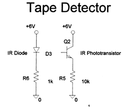
IR Beacon Input 1 (A/D 0) IR Beacon Input 2 (A/D 1) IR Beacon Input 3 (A/D 2) Tape Sensor Input (A/D 3) |
|
F0 |
Reset Switch (Active Low) |
|
G0 G1 G2 G3 G4 G5 G6 G7 |
DS3658 B, Shooter LEDs N.C. Back Indicator LED (not used) DS3658 C, Loader Power Relay Stepper Driver Step Size Select Stepper Driver Direction Select H-Bridge Channel A Direction H-Bridge Channel B Direction |
![]()

© Copyright 2001