The Yellow Jacket Robot Project Report
Loader
Dave Chisholm
Dave Chisholm
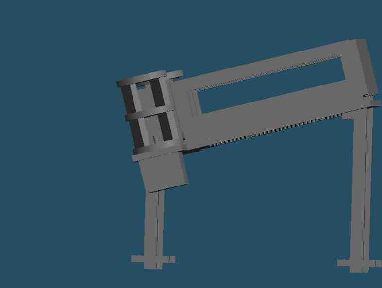
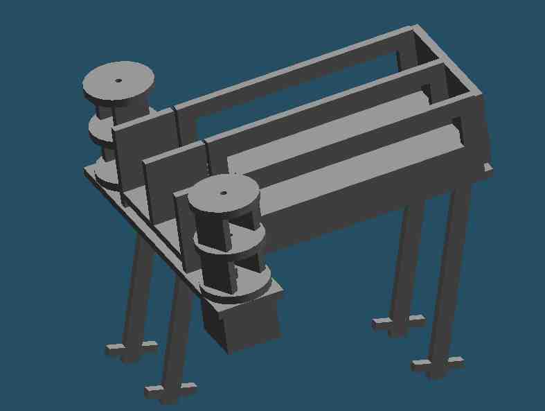
The loader focuses on holding the balls while not shooting, and reliably releasing them one at a time when necesary. The design consisted of a tray with two long slots for balls, each of which could hold four balls. Gravity would tend to pull the balls out of the end of the tray, since it was at an angle. At the end of the tray was a shutter, which could move from left to right and back, blocking the balls from falling out of one of the slots. The other slot was left open. Another shutter was spaced about 2 inches back from the first shutter, and when the first shutter was to the left, the second would be on the right. Thus the second slot would also be blocked, except the front ball in that slot would move beyond the first shutter. By having the shutters switch positions (ie one moves left, the other right simultaneously) we could release that front ball, but prevent any others from falling out, and also put another ball into a simlar, ready to fall position in the other slot. The shutters were moved by a .25 inch thick belt attached to their bottoms, which was wrapped around two wheels which were large enough in diameter to have a ball fit between the two shuters (2 inches). One of the wheels was attached to a stepper motor, and by pulsing the motor to move either clockwise or counter clockwise, we could have the shutter exchange positions. The diagram above is actually from an earlier design which called for a much wider belt with holes cut in it large enough for balls to fit through. Thus the wheels around which the belt is wrapped are 3 inches tall - the final design actually just used .25 inch tall wheels. The shutters were made of tinfoil, and had foamcore guides to prevent them from being pushed out of position by the weight of the balls. Our total ball capacity was 9 balls (4x2 + 1 in ready position), although it probably would have been possible to attach extensions to the trays to fit more balls.
The main issues I had to deal with once it was built, were drawing too much current, losing some steps due to friction and the shutters getting briefly caught on the balls or frame of the loader. Since the coil resistance of the motor was so low (~3 ohms), the current was both too much for the stepper motor controller board, which was limited to 350 mA per coil, and the power supply, which was limited to 500mA. I installed a 33ohm power resistor before each coil, which brought us under 350 mA (12V / 36ohms ~= 333mA, which i verifed with an ammeter). We replaced the power supply with one that could supply 1A. This worked fine by itself - however, we found that when we tried to use our driving motors at a hugh duty cycle while the stepper motor was drawing stall current, we could still draw too much current for our new power supply. (And our power resitors would also get very hot.) Since the PCB's for the stepper motor driver didn't allow you to shut off the current through logic, we installed a relay to turn off the current to the motor while we weren't loading. (We switched the relay using the 3658 DC motor controller, which took care of the relay's own current and inductive kickback issues.) This solution solved the power supply problem, and also cooled off the power resistors (although the power resistor were still within limits even without the relay - they were just annoyingly hot!)
The loader performed fine - even if it did get jammed, it could eventually unjam itself if it kept trying to load balls. Although we didn't need it, it was able to load the balls quite fast! One drawback was it's modest ball holding capacity - the other team held 4 times as many balls!
© Copyright 2001