The Yellow Jacket Robot Project Report
The Platform
David Black-Schaffer
David Black-Schaffer
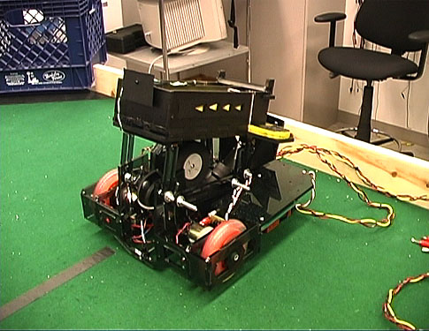
The platform design focused on moving the robot, holding the shooter, and mounting the electronics. As the loader was to be placed above the platform it was also designed to be as low as possible to meet the height requirements. The platform used exclusively tab and slot joints to both strengthen the design and to make it easier to work with before it was permanently glued. The design itself consisted of a flat U-shaped platform parallel to the ground with supporting beams underneath it. The platform was constructed of quarter-inch (nominal) smoked acrylic with half-inch tabs.
Two 4-inch diameter hard rubber scooter wheels mounted at the front right and left corners provided propulsion. It was noted that by placing the wheels at the front of the robot, rather than in the more traditional center location, the electronics could be easily fit underneath the platform on the sides. Furthermore, by so placing the wheels, the distance from the center of rotation to the center of the shooter was minimized. This potentially improved the rotational aiming accuracy. The two drive wheels were directly driven by two 100:1 geared DC motors. (Initial trials with 30:1 geared motors had proved unsuccessful.) As this configuration would place all of the strain on the motor shafts, additional nylon bearings and aluminum shafts were added on the outside of the wheels to help take the weight.
Since the robot had only two wheels, plastic glide pieces were attached to the bottom of the robot in the back to allow it to slide smoothly. The back section of the platform also contained cutouts for the power switch, power-on indicators, and ports for the power cables.
Both motors were driven by a single PWM output from the microcontroller through two H-bridges. The H-bridges drove the motors up to approximately 10V with a 32ms duty cycle. Two opposite-polarity LEDs were added to the motors to indicate the direction of the motor drive. The forward/reverse controls on the two H-bridges were individually controllable, but the PWM output was the same for both. While this arrangement enabled us to get away with using only two PWM channels, thus allowing us to use a PLS channel as well, it sacrificed some flexibility. As some part of the drive system was not perfectly matched (either the wheel mountings or the motors), the robot tended to drive with a curve to the left. Had each motor been on a separate PWM channel it would have been possible to calibrate them individually and drive in a straight line. Since our algorithm did not call for that much straight driving this was not deemed too significant an issue.
Besides holding the motors, the platform had to accommodate the shooter. This entailed leaving the entire center portion of the platform from the middle to the front edge open and adding the vertical adjustment rails for the shooter to the platform supports. Cutting out such a large space for the shooter resulted in a U-shaped platform design. As it was initially unclear whether the acrylic would be rigid enough in this design, the front piece was designed with a small cross portion connecting the two arms of the U. If the shooter were maximally lowered, however, this piece would potentially block the shooter. Therefore the crosspiece was designed to go down to within half an inch of the ground. Luckily, this did not cause a problem for the shooter and proved to be an excellent place to attach the tape sensor.
The vertical adjustment rails for the shooter consisted of cutouts in the vertical support pieces were raised to stick above the platform itself. By placing bolts with washers through these cutouts it was possible to adjust and then secure the shooter in a variety of positions. Two additional sets of vertical rails were added to the platform to allow attachment and adjustment of the loader.
With the wheels mounted at the front of the robot the entire underside portion of the platform not used by the shooter cutout was free for attaching the electronics. The sensor, H-bridge, and microcontroller boards were mounted first as they were the largest. The stepper driver and the shooter motor driver were then crammed into the vertical space besides each drive motor. This arrangement worked quite well. Not only did the PCBs look very cool behind the smoked acrylic, but also access to all but the stepper and shooter driver boards was easily accomplished by turning the robot upside down. Accessing the other two drivers was readily accomplished by removing the front and motor mounts. This approach worked fine until the motor mounts were glued in, at which point getting to them became quite tricky. The weight reducing cutouts in the beams underneath the platform proved invaluable for running wires between the various boards.
© Copyright 2001