The Yellow Jacket Robot Project Report
The Sensors
David Black-Schaffer
David Black-Schaffer
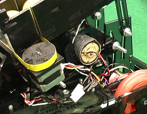
The two sensors included on the robot were both IR-based. The original design called for three beacon sensors and one tape sensor, but it was discovered that the beacon sensors were accurate enough that a single one was easier to implement.
The beacon sensors consisted of an IR phototransistor followed by a passive high-pass filter set at 196Hz, a variable gain stage, and a half-wave rectifier with a peak detector. The cutoff frequency of 196Hz was chosen to maximally reduce the 120Hz input from the room lights. This circuit output a relatively constant voltage that was directly dependent on the amount of 700Hz IR light. The filter did a reasonably good job of filtering out the IR from the 120Hz room lights. The peak detector did not include a bleed-off resistor and so the capacitor discharged slowly through the Op-Amp or A/D. This caused a noticeable delay in the decay of the output signal as the IR source was obscured, but given the rotational speed of the robot this was not deemed significant.
![]()
The beacon sensor was calibrated by placing the robot at the desired distance and pointing directly at the beacon. The gain was then adjusted until the output from the Op-Amp saturated. Unfortunately the Op-Amps with which this circuit was designed could not come close to reaching the power supply rails on the output. This limited the range of A/D values to approximately 0-150, but that proved to be more than sufficient accuracy.
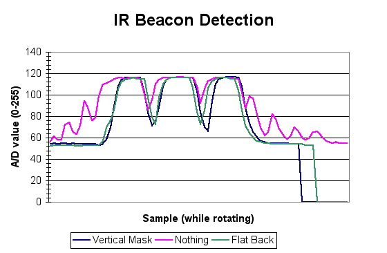
Extensive testing of the directionality of the IR sensors with various housings led to the conclusion that simply mounting the detector on a flat non-reflective background was sufficiently accurate. (See performance graph below. Data taken from rotating robot with all three beacons enabled.) Adding a vertical mask could indeed improve the accuracy, but tended to limit the vertical range. That limitation introduced the potential miss the beacons altogether. Without any mounting whatsoever the IR sensors picked up numerous reflections from the beacons.
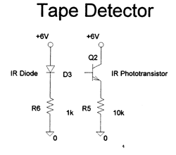
The tape sensor was designed in the simplest manner possible. The IR emitter was run in series a 1k current-limiting resistor from 6V to ground. The detector was configured in a common collector mode with a 10k emitter resistor. This configuration provided a 0 to 0.5V output swing and was readily detected by the A/D converter.
The only other sensor was a pushbutton used for starting the robot. This consisted of a switch with a pull-up resistor to provide logic-level outputs. As the switch was running off a 6V supply it was necessary to be careful to insure that the output never exceeded 5V.
© Copyright 2001