The Yellow Jacket Robot Project Report
The Shooter
David Black-Schaffer
David Black-Schaffer
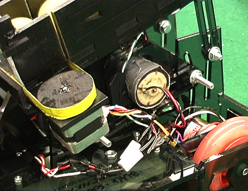
The shooter design selected was a pitching wheel arrangement. A foam wheel was selected to both reduce the weight and provide a good contact with the foam balls. The wheel was mounted from above into a corner-bent piece of 2.5" ABS pipe. This proved to be an excellent means of propelling the balls, but also required a very rigid and highly adjustable mounting to be accurate.
The shooter wheel was mounted directly on the shaft of an un-geared DC motor driven through the DS3658 driver from the second PWM channel. Due to inaccuracies in the drilling of the shooter wheel, it tended to vibrate when spun, potentially introducing inaccuracies in the aim. Of more significance, however, was the fact that the foam wheel had such a small rotational moment that each time it launched a ball it would slow down. To insure reproducible shooting it was necessary to pause between each shot to allow the wheel to spin back up.
Designing the shooter mount proved quite tricky. Ideally the mount would be fully adjustable, allowing the shooter to be aimed at any angle up or down, yet once secured it should be quite rigid. At the same time the mount should allow the motor height to be set independently of the shooter angle. The final design functioned by placing four 1/4-20 bolts through the sides of the shooter pipe on both ends parallel to the ground. These bolts then ran through mounting holes in the vertical platform supports. The rear pair of bolts simply passed through two mounting holes holding the back opening to the shooter slightly below the level of the platform wile allowing it to rotate. The front set of bolts ran into two curved tracks that allowed for –10/+20 degrees of elevation control. The shooter was then secured in place by tightening the nuts on the bolts. The bolts were placed in the flange portions of the shooter pipe insuring that they would not interfere with the path of the ball.
By designing a mount for the shooter motor that also attached to these bolts, it was possible to insure that once the motor was adjusted relative to the shooter pipe it would remain in the same relative position even as the shooter pipe was adjusted. This was accomplished by wrapping the shooting motor in thick rubber and using four U-shaped brackets secured with bolts to hold it fast. These brackets had mounting holes in them such that they too could be mounted on the pipe's mounting bolts.
This arrangement proved eminently flexible and quite reliable. Due to the inherent limitations of the LaserCam it was necessary to run the bolts securing the motor through the cross-section of the acrylic. This required very small bolts, but with four of them the motor was well secured.
In addition to securing the shooter itself, the bolts through the shooter provided additional rigidity to the entire platform as it effectively tied the two halves of the U-shape together.
© Copyright 2001