![]()
![]()
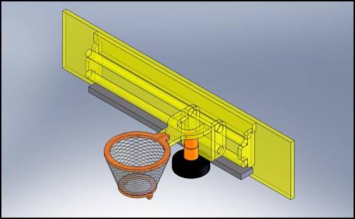
<Top>
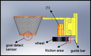
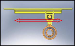
<Front>
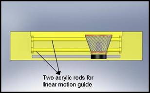
<Side>
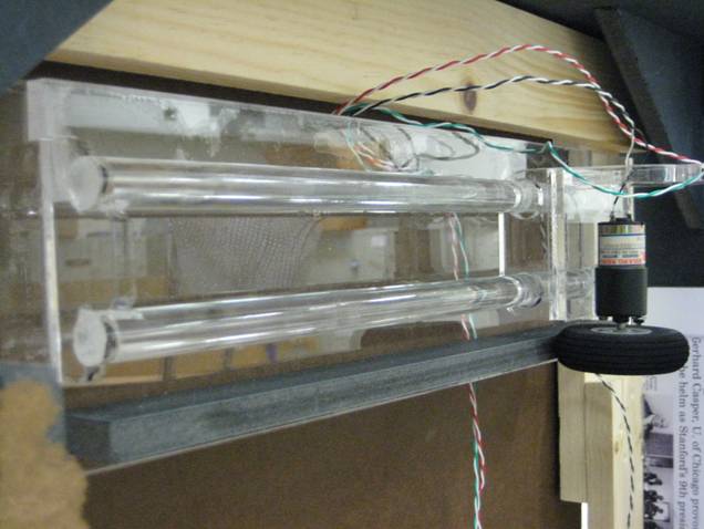
Mechanical
Part Specification
1. Motor : HSIANG NENG Geared Motor HN-27GB, 1ea
2. Parts : Acrylic sheets(from TAP Plastics), Masonite board(from Minton’s Lumber) and Laser CAM
processing
3. Movement
Driving Mechanism : A geared motor is
attached to the moving carriage, and a wheel is connected the motor.
The moving carriage is guided by two acrylic rods and
driven by the friction force
between a wheel and a guide bar.
![]()
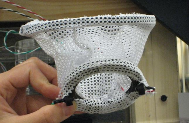
IR emitter and detector are located on
the opposite side of the hoop each other that they detect a ball going through
the hoop.
![]()
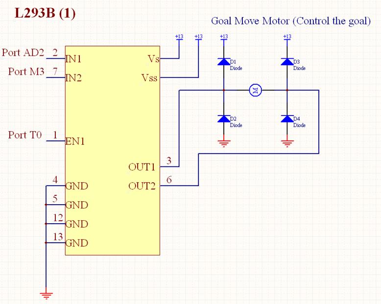
Goal move motor (gear motor) is controlled
bi-directionally by L293B.
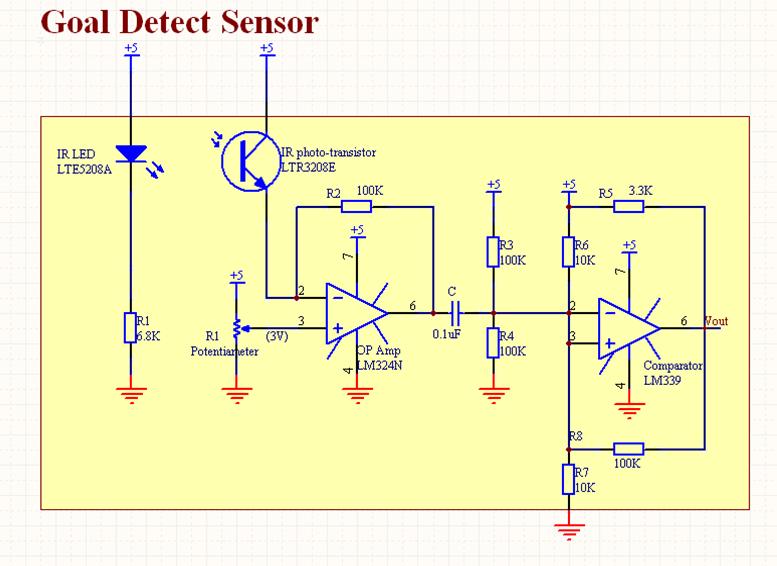
The circuit for goal detect sensor is composed of Op-amp
and comparator. A
trans-resistive circuit is used to generate the current when IR signal is
received. The output of the trans-resistive circuit is connected to LM324 in
order to amplify the signal. Finally the output of the amplifier is connected
to a high pass filter which is connected to a Schmitt trigger implemented with
LM339 in order to create a clean, noise free digital signal. The output of the
Schmitt trigger is tied to the input of the pin AD1 of a 9S12C32 to interface.
Backup
Calculations
V+ of LM324 was connected to the
potentiometer. The voltage of the potentiometer was 3V.
The output voltage of the high pass
filter swung between 2 V and 4 V with the voltage difference of 2 V. Therefore,
the following Schmitt trigger (Rpullup = 3.3 KΩ, R6 = 10 KΩ,
R7 = 10 KΩ, and R8 = 100 KΩ) where

can be used.
Since the amplifier and the Schmitt
trigger are inverting ones, the output of the circuit is low when there is a
goal and high otherwise.