Electronics Description:
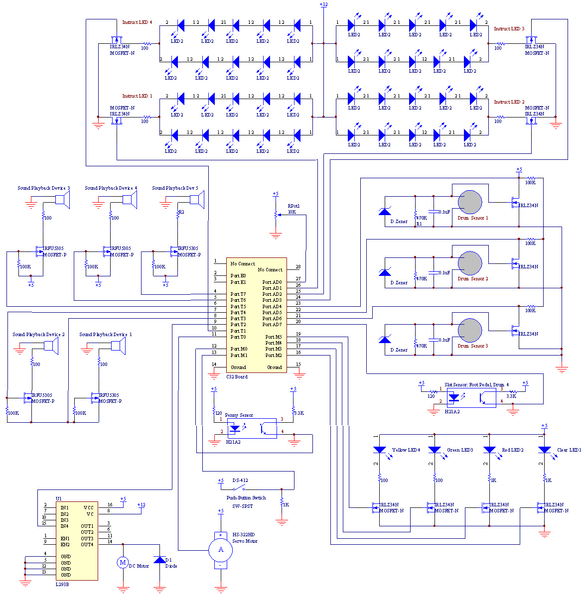
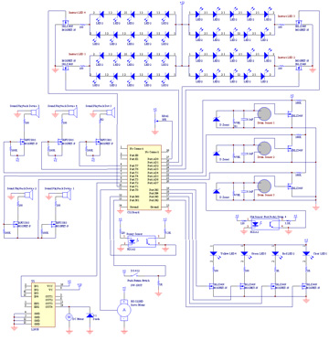 All the inputs and outputs to DrumHero connected to the C32 board and were powered by a 12V and 5V power supply. Inputs included piezoelectic sensors, a push button, slot sensors, and a potentiometer. Outpus included LEDs, sound generators, a servo motor, and a DC motor. The electronics fit on two protoboards. Click the overall schematic image to the right to view a larger version that you can zoom in.
Electrical Components:
- Drum LEDs
- Drum Sensors
- Drum Sound Generators
- Instruction LEDs
- Difficulty Level Selector Potentiometer
- Start Button
- Score Indicator Servo Motor
- SWAG DC Motor
- Penny Insert Slot Sensor
- Foot Pedal Slot Sensor
C32 Board Pin Connections:

Drum LEDs
Components:
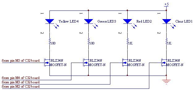
- 1 x large clear LED
- 1 x large red LED
- 1 x large green LED
- 1 x large yellow LED
- 2 x 100 Ω resistors
- 2 x 1 kΩ resistors
- 4 x IRLZ34N N-channel MOSFETs
The circuit for the drum LEDs consists of an LED, a resistor, an N-channel MOSFET and a 5 V power supply in series. The N-channel MOSFETs are used as low side switches, with the gates of the MOSFETs connected to digital output pins of the C32 board. When the output pin is low, the MOSFET and LED are off. When the output pin is high, the MOSFET and LED are on. The resistors are sized so that the current flowing through the circuit is less than 40 mA. The yellow and green LEDs require a larger amount of current to match the brightness of the red and clear LEDs.
Drum Sensors
 Components:
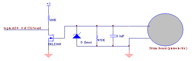
- 3 x piezoelectric drum sensors (from First Act Discovery 5-pad Digital Drum Kit)
- 3 x 470 kΩ resistors
- 3 x 100 kΩ resistors
- 3 x zener diodes
- 3 x 0.1µF capacitors
- 3 x IRLZ34N N-channel MOSFETs
The drum sensors are piezoelectric force sensing pads that were obtained from an electronic drum kit. When force is applied to the pad, current flow is generated and a voltage drop is measured across the leads of the drum sensor. Voltage drops of up to 25 V were measured across the drum sensor when it was struck by a drum stick.
To digitize the signal from the drum sensor, it is placed in parallel with a resistor, a capacitor, and a reverse-biased zener diode. When the drum is struck, current flow is generated through the circuit. The resistor is sized so that the voltage drop across the circuit without the presence of the reverse-biased zener diode is greater than 5 V when the drum is struck. The addition of a reverse biased zener diode then ensures the voltage drop is across the circuit is no more than 5 V. When the drum is struck, the diode goes into reverse breakdown and forces the voltage drop to be the reverse-breakdown voltage of 5 V. The capacitor adds some time delay to the high state of the signal. Therefore, when the drum sensor is not struck, the high side of the circuit is at 0 V. When the drum sensor is struck, the high side of the circuit is at 5 V.
To further ensure a clean digital signal, the high side of the circuit described above is connected to the gate of an N-channel MOSFET, which is in series with a resistor and a 5 V power supply. The low side of resistor is connected to a digital input pin of the C32 board. The N-channel MOSFET acts as a low side switch. Therefore, when the drum sensor is not struck, the MOSFET is off and the input pin is high. When the drum sensor is struck, the MOSFET is on and the input pin is low.
Drum Sound Generators
 Components:
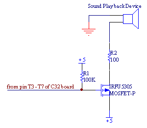
- 5 x “Build-A-Sound” sound playback devices (from Build-A-Bear)
- 10 x 100 Ω resistors
- 5 x IRFU5305 P-channel MOSFETs
The drum sound generators are “Build-A-Sound” sound playback devices made by Build-A-Bear. The device's interface consists of two buttons: pressing one button allows the user to record a sound, pressing the other plays it back. Four different drum sounds and one bad sound were recorded on five devices. Pressing the play button causes a pulse of current to flow between two wires on the device’s PCB.
To control the device with the C32 board, wires were soldered onto the device’s PCB at the two identified locations, and were then placed in series with a resistor, a P-channel MOSFET, and a 5 V power supply. The gate of the P-channel MOSFET is connected to a digital output pin of the C32 board. A pull-up resistor is used to maintain the gate at 5 V when the the output pin is floating. The P-channel MOSFET acts as a high side switch. When the output pin is pulsed low, a pulse of current flow between the two wires on the device’s PCB and the recorded sound is played.
Instruction Number LEDs
Components:
- 40 x medium green LEDs
- 4 x 100 Ω resistors
- 4 x IRLZ34N N-channel MOSFETs
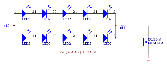
The circuit for the LEDs that light the instruction numbers consists of two sets of 5 LEDs in parallel, which is in turn in series with a resistor, an N-channel MOSFET, and a 13 V power supply. The N-channel MOSFETs are used as low side switches, with the gates of the MOSFETs connected to digital output pins of the C32 board. When the output pin is low, the MOSFET
LEDs are off. When the output pin is high, the MOSFET and LEDs are on. The resistors are sized so that the current flowing through the circuit is less than 40 mA.
Difficulty Level Selector Potentiometer
Components:
- 1 x 10 kΩ linear taper potentiometer
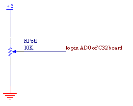
The circuit for the difficulty selector potentiometer consists of a potentiometer powered by a 5 V power supply. The potentiometer slider is connected to an analog input of the C32 board.
Start Button
 Components:
- 1 x push-button SPST momentary switch
- 1 x 1 kΩ resistor
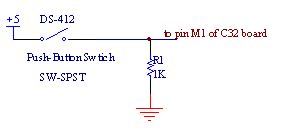
The circuit for the start button consists of a momentary switch in series with a resistor and a 5 V power supply. The high side of the resistor is connected to a digital input pin of the C32 board. When the momentary switch is open, the input pin is low. When the momentary switch is closed, the input pin is high.
Score Indicator Servo Motor
Components:
- 1 x Hitec HS-322HD servo motor
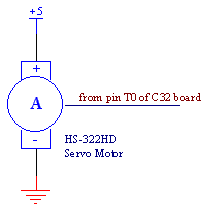
The score indicator servo motor is powered by a 5 V power supply and the signal lead is connected to a PWM output port of the C32 board. Depending on the duty cycle of the PWM signal outputted to the servo, the position of the motor shaft changes.
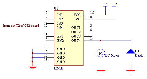
SWAG DC Motor
Components:
- 1 x DC motor
- 1 x L293B quad push-pull driver
- 1 x diode
The circuit for the SWAG DC motor consists of a DC motor, a quad push-pull driver, a diode, a 5 V power supply, and a 13 V power supply. The circuit is set up so that the driver controls the unidirectional motion of the motor. The signal pin of the driver is connected to a PWM output pin of the C32 board. Depending on the duty cycle of the PWM signal outputted to the driver, the motor speed varies. For a 0% duty cycle, the motor is off. For a 100% duty cycle, the motor is on at its maximum speed.
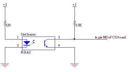
Penny Insert Slot Sensor
Components:
- 1 x H21A2 opto-interrupter
- 1 x 120 Ω resistor
- 1 x 3.3 kΩ resistor
The penny insert slot sensor consists of an opto-interrupter, resistors, and a 5 V power supply. The high side of the opto-interrupter’s phototransistor is connected to a digital input pin of the C32 board. When the light beam between the photodiode and phototransistor of the opto-interrupter is broken, the input pin is at 5 V. When the light beam is uninterrupted, the input pin is at 0 V.
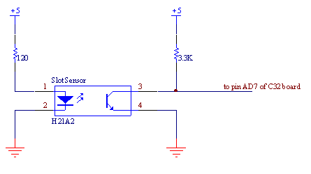
Foot Pedal Slot Sensor
Components:
- 1 x H21A2 opto-interrupter
- 1 x 120 Ω resistor
- 1 x 3.3 kΩ resistor
The foot pedal slot sensor consists of an opto-interrupter, resistors, and a 5 V power supply. The high side of the opto-interrupter’s phototransistor is connected to a digital input pin of the C32 board. When the light beam between the photodiode and phototransistor of the opto-interrupter is broken, the input pin is at 5 V. When the light beam is uninterrupted, the input pin is at 0 V.
|
|

 All the inputs and outputs to DrumHero connected to the C32 board and were powered by a 12V and 5V power supply. Inputs included piezoelectic sensors, a push button, slot sensors, and a potentiometer. Outpus included LEDs, sound generators, a servo motor, and a DC motor. The electronics fit on two protoboards. Click the overall schematic image to the right to view a larger version that you can zoom in.