Mechanical
Design and Dimensioning
Overall Structure
The
main structure was constructed from ½” foam core and hot glue. The bowling alley ramp was made with an angle
of 2.7° by making the front supports 1.5” taller than the back supports. The angle was chosen so that the pennies
would not curve too much, as a larger angle would have made them curve toward
the middle of the ramp. The majority of
the indicators were mounted in the display panel above the end of the ramp. The bowling pins were also mounted to this
panel. The start button and the
difficulty selector are mounted in their own panel on the front right side of
the ramp. The prize dispenser is
underneath the bowling alley ramp near the front panel. A trap door was included in one of the side panels
to allow access to the components underneath.
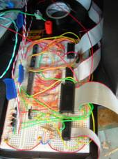
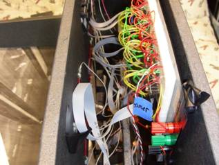
The main circuit boards, microcontroller, and power supply were also
underneath the ramp. The circuit board
for the seven-segment LEDs is supported on a ledge
behind the display panel. The
substructures of the game are described below.
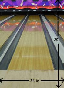
Bowling Alley Ramp
Dimensions
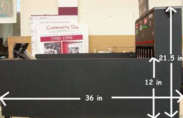
Side Panel Dimensions
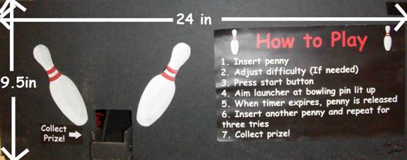
Front Panel Dimensions
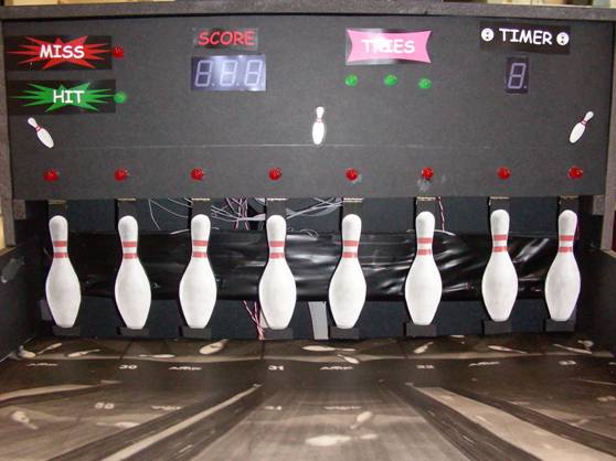
Display Panel
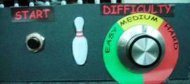
The start button and the
difficulty selector
Trap door to allow access
to components
Stepper motor circuit
board for Prize Dispenser
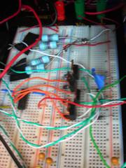
Main circuit board
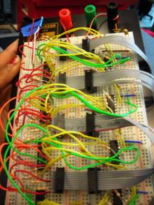
Seven-segment LED displays
for score and timer circuit boards
Behind display panel
Launch Mechanism
The
launch mechanism consists of a foam core ramp, a foam core penny insertion
slot, an optointerruptor, an aluminum guiding ramp, a
wood dowel for an aiming handle, and a solenoid with a gate attached, all
supported on a cardboard disk. The optointerruptor is mounted directly behind the penny
insertion slot and in front of the guiding ramp so that the penny will be
detected and then roll into its starting position. The guiding ramp has a milled lengthwise 0.1”
slot (slightly larger than the width of a penny). Near the top of this ramp is milled an
additional slot for the solenoid gate to block the penny from escaping. The bottom of the guiding ramp touches the
bowling alley surface so the penny will release smoothly from the
launcher. The solenoid gate is
constructed from small pieces of cardboard and is hot glued onto the solenoid
shaft. The solenoid is supported by
pieces of foam core to raise it to the appropriate height. All of these components are mounted onto the
foam core ramp, which gives the penny a large starting angle so it will gain
enough speed to hit a bowling pin. This
ramp is glued to the cardboard disk, which is connected to the bowling alley
surface with a pivot. The wood dowel is
glued to the disk to allow the user to easily aim the ramp at the correct
bowling pin.
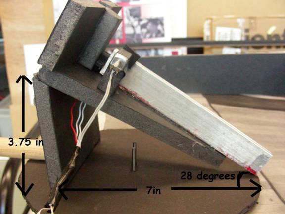
Penny launcher
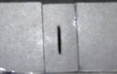
Foam core penny insertion
slot
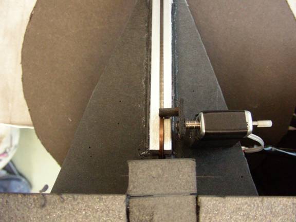
Top view of penny launcher
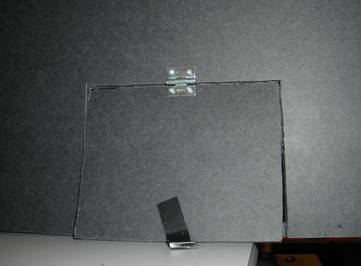
Bowling Pins and Their
Sensors
The
eight bowling pins are cut from cardboard, and are mounted to the display panel
with ¾” wide hinges. A small cardboard
tab is affixed to the back of each pin to block the optointerruptor
when the pin is hit.
The
original idea for detecting a “hit” was to use an array of switches mounted to
the top of the bowling pins that would be closed when the pin was hit. However, the team was unable to find switches
that would activate with the small force provided by the penny. Since optointerruptors
were readily available, we devised a way to use these instead.
An
array of eight optointerruptors is mounted directly
behind the bowling pins on a foam core strip.
To make sure the bowling pin tabs were precisely aligned with the optointerruptors, the optointerruptors
were placed first, and then the correct location for each tab was determined.
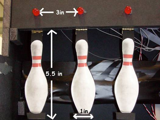
Dimensions of bowling pin
Prize Dispenser
The
prize dispenser uses a stepper motor to give out Skittles based on the number
of motor rotations. The original
dispensing idea was a vertically mounted wheel with grooves cut into its
circumference. Skittles would drop one
by one from a reservoir into these grooves as the wheel was rotated by the
motor, and then drop into a prize collection area. The problem with this idea was that the
opening in the reservoir needed to be much larger than the thickness of the
wheel in order for the Skittles to drop, so there was little control over where
they would go.
Vertical prize dispenser
wheel
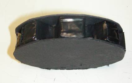
We
modified this concept by attaching the motor to a horizontal wheel with four
holes cut into it. The Skittles
reservoir was placed right above the wheel, and as the motor turns each hole
passes by the reservoir outlet and Skittles fall through the hole and into the
collection area.
Horizontal prize dispenser
wheel
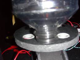
The
reservoir is made from a large empty Gatorade bottle, cut to the right
height. The horizontal wheel is foam
core, and the holes are lined with PVC pipe to create a smooth, uniform
surface. The collection area consists of
a cardboard ramp that guides the Skittles from the horizontal wheel to the
bottom surface of the game, and a horizontal cardboard surface flush with the
bottom of the game. The horizontal
surface has tall cardboard walls so that the Skittles will remain in the area
until the user collects them for their prize.
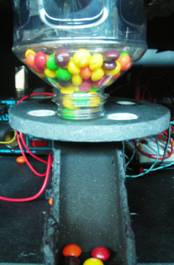
Reservoir with skittles
and horizontal foam core wheel
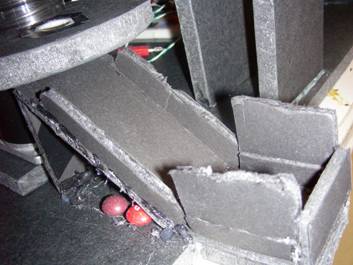
Ramp to guide skittles for
prize collection