Circuit Schematics
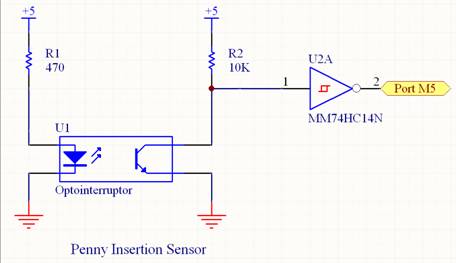
This circuit is
used to sense the insertion of a penny. Before
the penny is inserted, current is flowing through the detector (transistor)
side of the optointerruptor, and Port M5 is HI. When the penny blocks the optointerruptor,
Port M5 goes low. The hex inverter
with Schmitt trigger (74HC14) ensures a clean digital signal from 0 to 5 V. The typical positive going threshold for the
74HC14 is 2.38 V, while the negative going threshold is 1.40 V.
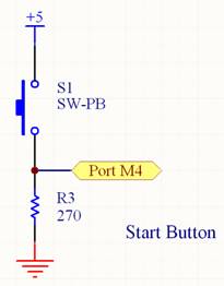
This simple switch
circuit outputs high when the switch is pressed and low when the switch is
not pressed. The resistance value was
chosen so that the current through the switch wasnot too high. The maximum current is approximately 18.5 mA, which is within the limits of the switch.
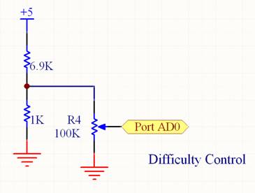
This circuit is
used as an analog input to the A/D controller in the C32. It is used to select the difficulty level of
the game. A large total resistance
was chosen because the potentiometer is only being used as a voltage reference,
so it does not need to source or sink much current. A voltage divider was tied to the high side
of the potentiometer because the A/D port of the C32 only accurately read
voltage values up to about 2 V.
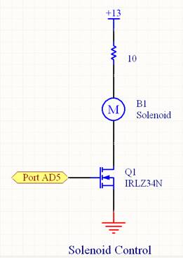
This circuit is
used to activate the solenoid. When
Port AD5 is high, current runs through the solenoid and it is activated. The IRLZ34N was chosen as the transistor because
it is able to tolerate a maximum drain-to-source voltage of 55 V, and up to
30 A of current. The resistance of
the solenoid is 2 Ω, the internal resistance of the IRLZ34N is 0.035
Ω, and the power resistor is 10 Ω, so the current through the solenoid
is 1.08 A.
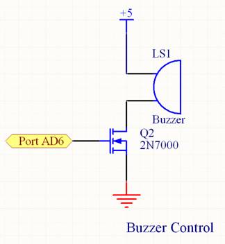
The buzzer is activated
when Port AD6 is high. The 2N7000 MOSFET
is used because the current in this circuit is not too high (the resistance
of the buzzer is 250 K). To activate the buzzer, Port AD6 is pulsed high/low
a few times near the buzzer's resonant frequency, and then left high for the
desired length of time. The pulsing
is needed to ensure that the buzzer will always turn on when desired.
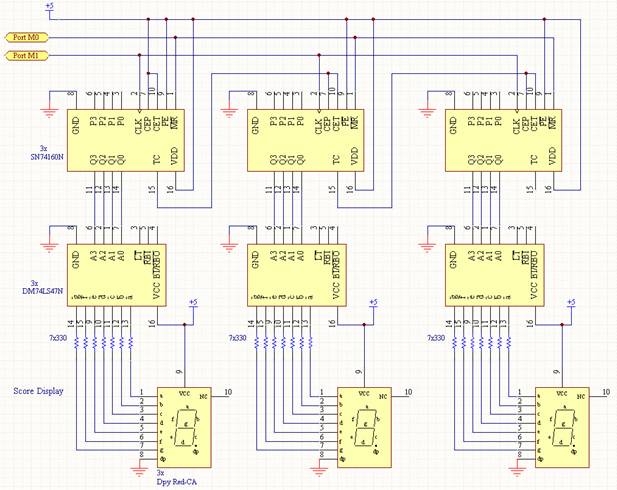
This circuit is
used to control the score display. It
consists of three seven-segment displays controlled by three binary-coded-decimal
(BCD) counters, which individually control each display. They are cascaded together so that we can count
up to 999 while using onlytwo output ports from the microcontroller. The BCD counters are driven with a set of clock
pulses from Port M1, which causes them to count up to the desired number. Port M0 is the ~CLEAR bit, which is held high
until the display needs to be cleared, when it is pulsed low. The BCD counters are connected to BCD-to-seven-segment
decoders, which translate the four-bit BCD numbers into the seven-segment
LED configuration. These are then connected
into common-anode seven-segment LED displays.
The resistance values were chosen to be 330 Ω because this gives
a reasonable amount of current to the display segments so they are clearly
visible.
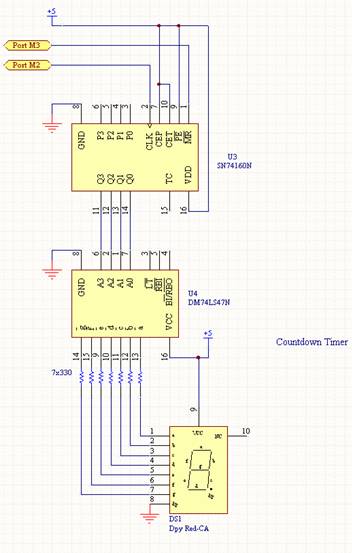
The countdown
timer circuit is identical to the score circuit, except it only uses one stage
of BCD counter, BCD-to-seven-segment decoder, and seven-segment LED.
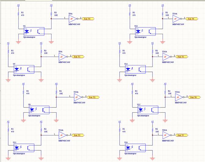
The switch circuit
uses optointerruptors just as in the penny insertion
sensor. Their components and
functionality is identical to that circuit, and each switch is read in by its
own port of the microcontroller.
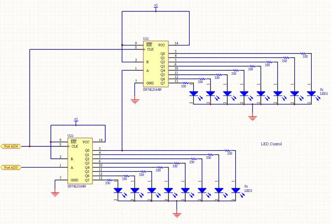
This circuit uses
two serial in/parallel out shift registers (74LS164) to control 16 separate
LEDs. These LEDs are used to light the bowling pins, indicate number of
tries remaining, and display a hit or a miss.
The shift registers are linked together so that all 16 LEDs
can be controlled using only two microprocessor ports.
The desired output configuration is input to the first shift register's
serial input from Port AD3, and it is shifted to the next parallel shift register
port each time the clock is pulsed (Port AD4), until the correct LEDs
are lit. The shifting is done very
rapidly so that it is not visible to the human eye.
The 330 Ω resistors were again chosen for the correct amount of
current and light intensity in each LED.
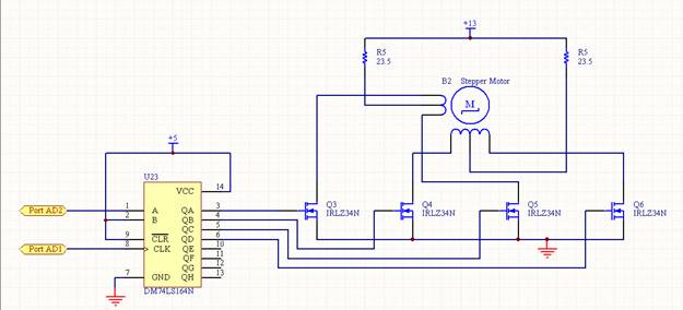
A six-wire unipolar stepper motor is used to drive the prize
dispenser. It consists of two windings,
each with a center tap. The center taps
are connected through a resistance of 23.5 Ω to 13 V, and the winding ends
are each connected to separate IRLZ34N power MOSFETs. A serial-in/parallel-out shift register is
used to turn on each of the MOSFETs in sequence. When a MOSFET is turned on, current flow through
the motor winding that is connected to it.
The drive sequence for this application turns on only one winding at a
time, or A/B/Ainverse/Binverse. The windings turn on in order from left to
right in the above diagram. The
resistance limits the current in the circuit, and the resistors used are two
parallel 47 Ω power resistors for each center tap.
C32 Board
Connector Pin Assignments
C32 Connector
Game C32 pin pin C32 Game
No Connect 1 28
No Connect
Port E0 2 27
Port AD0 Difficulty Control
Port E1 3 26
Port AD1 Prize Dispenser Data
Switch 8 Port T7 4
25 Port
AD2 Prize Dispenser Clock
Switch 7 Port T6 5
24 Port
AD3 LED Data
Switch 6 Port T5 6
23 Port
AD4 LED Clock
Switch 5 Port T4 7
22 Port
AD5 Solenoid Control
Switch 4 Port T3 8
21 Port
AD6 Buzzer Control
Switch 3 Port T2 9
20 Port
AD7
Switch 2 Port T1 10
19 Port
M5 Penny Insertion Sensor
Switch 1 Port T0 11
18 Port
M4 Start Button
Score Clock Port M0 12
17 Port
M3 Timer Data
Score Data Port M1 13
16 Port
M2 Timer Clock
Ground 14 15
Ground