Optical Encoder
Overview
An
optical encoder was used to detect the position of the spinning wheel in the
second portion of the game. The encoder consists of three tape sensors which
detect reflected infrared light from two sensor rings. The sensor rings and
tape sensor positions are shown in Figure 1. The outer sensor ring had a
pattern of 16 alternating white and black squares corresponding to the 16
available prices shown on the front of the wheel. The primary tape sensor was
aimed at this ring and incremented a counter each time it detected a rising
edge (going from black to white) or a falling edge (going from white to black.)
In this way, the encoder tracked the relative movement of the wheel.
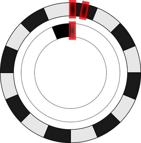
Figure 1.
Sensor rings and tape sensor positions for the optical encoder.
A
secondary sensor used to determine direction was positioned on the outer ring ½
of a division away from the primary sensor. By observing which sensor had a
rising or falling edge first, the direction of the wheel’s rotation was
inferred.
A second sensor ring, consisting of a single black
square, was used to calibrate the absolute position of the encoder. Once per
rotation, the calibration tape sensor detected the black square and reset the
counter to reflect an accurate absolute position. While the tape sensor
hardware was very reliable and accurately detected transitions at high wheel
speeds, the speed at which the three tape sensor ports could be polled by our
C32 processor was not fast enough to ensure accurate counts over long periods
of gameplay.
Supplementary
Electronics
The
output from each tape sensor required signal conditioning before being fed into
the C32 processor. When optimally positioned, the tape sensors swung between
approximately 2.5 and 4.0V as the black and white squares passed the sensors.
This signal was used to generate clean, bounce-free transitions between 0 and
5V by passing the sensor output through a LM339 quad comparator with hysteresis
implemented.
Construction
The
primary sensor ring was approximately 11” OD/9” ID and the secondary sensor
ring was approximately 8.5” OD/6.5” ID. The rings were each printed on sheets
of 13x22 card stock at Kinko’s and were cut out and attached to the back of the
wheel with the transitions lined up with the prices displayed on the front. The
tape sensors were mounted approximately 1” from the back face of the wheel and
were attached using brackets cut out on the LaserCAM. While the spec sheet for
the tape sensors gave a specific distance for optimal signal, we found that
moving the sensors back further increased our signal and gave more reliable
transitions.