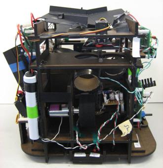
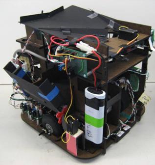
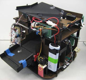
Overview
Alastair’s
chassis is modular by design to facilitate installation, removal, testing,
tuning and integration of individual subsystems. While much of the chassis is constructed of
laser-cut masonite, foam-core is favored for less structurally demanding
components due to its prototyping utility and ease of manual manipulation. The use of interlocking joints is the
dominant method of mating masonite parts as components can be mounted without
the use of adhesives or additional mounting hardware. Non-destructive removal of individual parts
and entire subsystems is also possible.
Click on
the labels for detailed description
Click here for detailed CAD drawings
Front Right
Back Left
Top Bottom
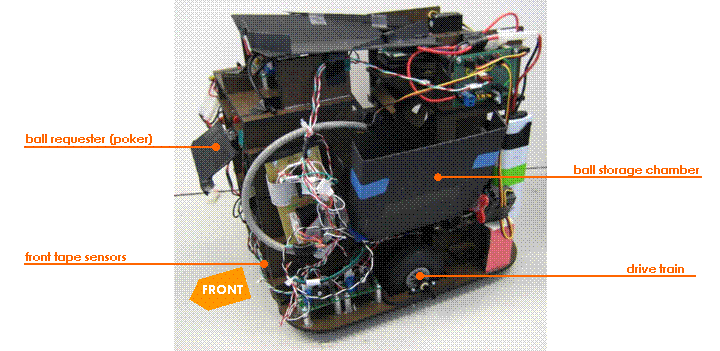
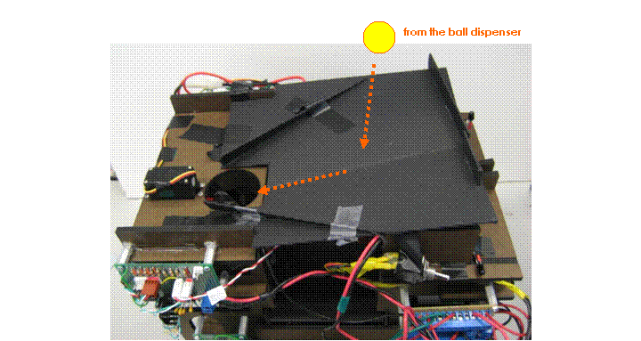
Ball Requester (Poker)
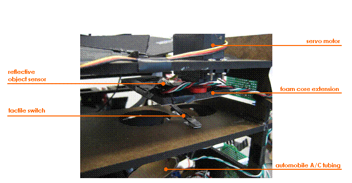
The
mechanism for ball request is actuated by an HS311 servo motor outfitted with a
foam-core extension. The extension
measures 6” in width and makes contact with the ball request trigger with an
edge that is parallel to the front face of the robot. To request a ball, it is swept vertically
from low to high until it is parallel to the ground. When the extension is pressed flush against
the ball request trigger, it serves as a flat, straight surface, which when
coupled with software, enables Alastair to reposition himself to achieve an
ideal trajectory for his shooter.
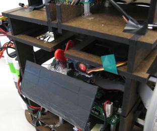
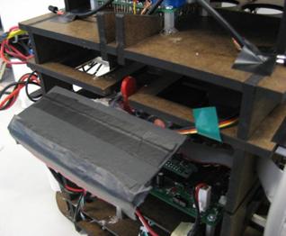
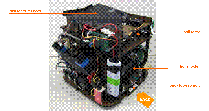
Ball Receive Funnel
Constructed
of foam-core, the ball receive funnel serves to direct requested balls to the
ball sorter. It can be easily lifted off
and put aside for access to the circuits and mechanisms underneath it.
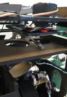
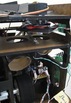
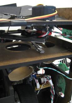
Ball Sorter
The
ball sorting mechanism is actuated by an HS311 servo motor outfitted with a
foam-core extension and a QRD1114 reflective object sensor. The extension consists of one layer of
foam-core with a square segment removed.
A ball may sit freely in this hole and rolls easily with changing
positions of the extension. The
reflective object sensor is located on the edge of the hole in close to where
received balls sit. This unit is mounted
between two levels of laser-cut masonite which are spaced a vertical distance
of a single ball apart. The upper level
has a single circular opening to allow for receipt of a ball. The lower level has two circular openings
identical to the upper level, which lead to either the ball storage chamber or
to the ball shooter. Balls are routed to
these two locations using automobile air conditioner tubing. Between the openings in the lower level sits
a tactile switch that activates when a ball is received. The trigger is modified to lower the force
necessary to activate the switch – a ball would otherwise be unable to do
so.
![]()
![]()
default position sorting to the storage chamber sorting to the shooter
Ball Shooter
The
ball shooter consists of a single Maxon motor and a modified foam wheel. Circular acrylic pieces sit inside the wheel
to increase its inertia and subsequent shooting consistency. The wheel and acrylic are mounted to a
flanged shaft collar which in turn is mounted to the motor shaft. Location and stability of the automobile air
conditioner tubing leading from the ball sorter to the shooting wheel is
critical in determining ball trajectory and speed. Tuning was accomplished by hand and made
permanent using foam-core placeholders and hot glue. While sturdier solutions were considered,
this method was the simplest and quickest to prototype. After running for many cycles, it continues
to achieve near perfect accuracy.

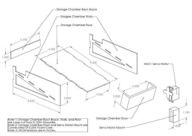
Ball Storage Chamber
The
ball storage chamber is made of laser cut masonite and lined with foam-core
inserts. It is slanted to guide balls
towards the left side of the robot upon receipt and is sized to loosely fit ten
balls. Its door is made of several
foam-core pieces and is actuated using an HS311 servo motor. When open, it forms a plank with side walls
to guide the balls out of the chamber.
The length of the plank allows Alastair to deposit balls into Goal 3
while lining up on the green tape and without making direct contact with the
goal.
storage chamber closed storage
chamber opened
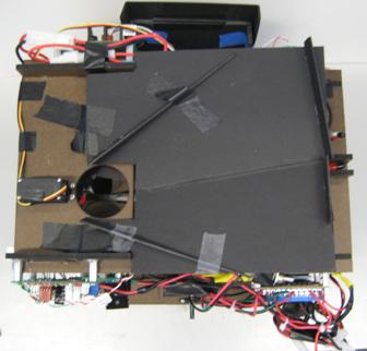
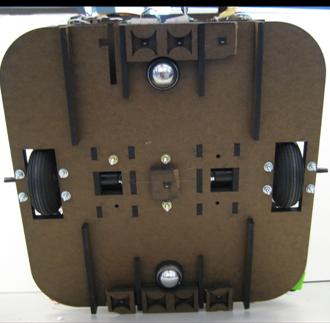
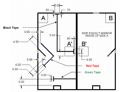
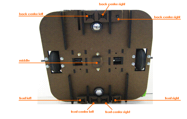
Tape Sensors
A total of eight reflective object sensors are used
for tape sensing and following. There
are four sensors in the front: center left/right, and left/right sensors (see
photo below). The centers of the two
front center sensors are strategically placed one tape width apart so that they
can detect the robot’s deviation from the tape with equal sensitivity in both directions
(left and right of tape). The two front center sensors and the center sensor
are used to detect and follow the tape.
The front right and front left sensors are placed
4 inches apart from each other to detect the “T” intersection in front of the
ball dispenser and at goal #3.
The three back sensors are used to line up at
goal #3 on side A of the playing
field. The storage chamber opens to the left side of the
robot. Therefore, on side B of the playing field, it can move forward and
follow the tape to align itself to dump the balls out to goal #3, but on side
A, it is required to make an 180 degree turn and follow the tape backwards using
the three back sensors until it hits the “T” intersection at goal #3. The two back center sensors are used in
conjunction with the center one to track along the straight portion of the tape
and the back right sensor is used to stop at the “T” intersection.
The reasoning behind the funky shape of the
reflective object sensor mount is to linearize the sensor signal. However,
because the sensors are not mounted far enough off the ground, the shape of the
mount has no significant effect on the sensor signal.
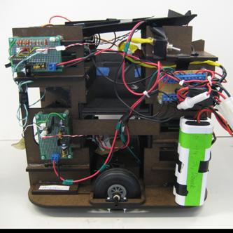
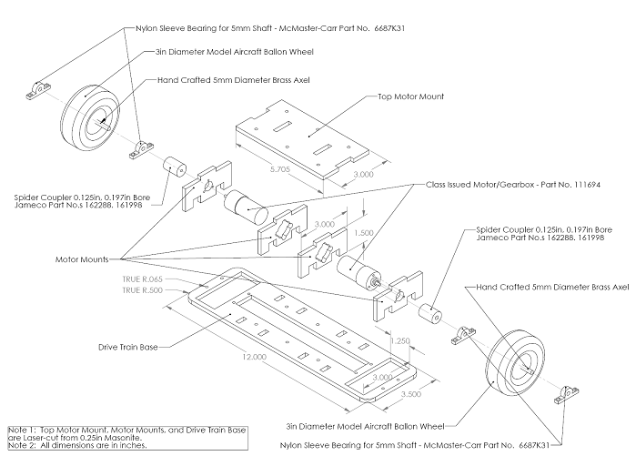
Drive Train
The drive train is built for the sole purpose of
mounting two Maxon motors to two balloon wheels. To allow for ease of assembly, installation,
and removal, it is built on its own base, which is affixed to the chassis base
using up to six nuts and bolts. Furthermore,
the drive train is symmetric about its center axis. Each motor faces away from the center of the
drive train, rests within two mounting piece, and is screwed to the mount on
its shaft side. A stabilizing piece
mates to the four mounting pieces.
Screws used to mount the drive train to the robot chassis will be fed
through the top motor mount, the drive train base, and finally thought the
chassis base. A brass axel of 5mm
diameter is press fitted through each balloon wheel. Each axel is supported on either side of its
wheel by plastic pillow blocks and connected to its respective motor using
spider couplers. While convenient, this
method of connection introduces significant slop into the drive system. To counteract these effects, the axels are
keyed to allow for better mating to the spider coupler and the set screws
shipped with the spider couplers were replaced with heavy duty M3, Philips
head, steel screws. Since higher torques
may be applied to the Philips heads on the replacement set screws, it was
possible to “dig” these heavy duty screws into the axels and motor shafts. Also, removable Lock-Tite was applied to
these new screws to guard against unscrewing due to vibration and repetitive
use, and the entire coupler was taped together to reduce compression of the
rubber spider. The combination of these
measures resulted in a drive train of minimum slop and subsequently reduced
overshoot during high speed maneuvers.