Mechanical Overview
Our mechanical objective was to provide a platform that
facilitated stereo beacon detecting, tape sensing, encoder reading, drive motor
velocities between 50 and 100% duty cycle, ball detection, sorting, dispensing
for both goals 3 and 2, and impact sensing for goal 3 and the ball dispenser.
|
|
Stereo
Beacon Detecting We found that beacon
following was optimal when we used stereo beacon detecting. This consisted of two IR detectors side by
side separated by a vertical panel (see Fig 1). We would drive forward when both detectors
detected a particular beacon. If only
one saw the beacon, the robot would turn in the corresponding direction until
both detectors detected the beacon before driving forward. These were placed at an elevation of
precisely 10”. There were two stereo
beacon detecting sets. The first sits
centered about the goal 3 ball dispenser.
The second sits centered about the goal 2 ball dispenser. This way the robot can align each dispenser
accurately with the corresponding goal’s beacon. Tape
Sensing Tape sensors were placed as
far forward as possible to maximize stability (see Figure 2). They were also aligned with the top ball
hopper as we used the tape sensors to align with the ball dispenser. Two tape sensors were placed in the center
for tape following. The outermost tape
sensors were there for tape crossing detection. Goal
3 Dispenser Goal 3 dispenser was a rectangular
hopper with a release bar (see Figure 2).
The objective was to set a strip of balls into goal 3 to maximize ball
distribution density. A door lock
motor pulled the bar to prevent balls from falling out and pushed it to
release them. Transmission The transmission consisted of
a belt drive (see Figure 2). The maxon motors drove a drive pulley through a spider
coupling which in turn drove the wheels through the belt. The transmission choice was selected to
allow flexibility in the design should a different mechanical advantage be
desired in the future. The specific
mechanical advantage we chose enabled us to operate at a drive pulse of
50-100% duty cycle for almost all tasks. Encoder
Reading We found early on that our
performance was adversely affected by varying battery voltages. To reduce our sensitivity to batter
voltages we implemented encoders on each of ou Ball
Detection and Sorting The balls would fall from the
dispenser onto a sloped ramp which would take the balls into the corner of
the robot to the sorter (see figure 4).
The sorter consisted of a sloped circular surface with a slot cut in
it and mounted to a motor. An IR
emitter and detector sit above the sorter and anothe Goal
2 Dispenser Getting balls into goal 2
required that we shoot the balls (see Figure 5). Anothe Goal
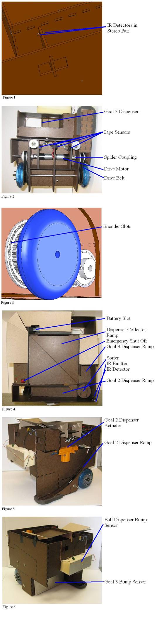
3 Bump Sensor The bump sensor consisted of
a single momentary switch with a large metal place across the front of it
(see Figure 6). This way, force
contact with any part of the metal surface would trigger the sensor. Ball
Dispenser Bump Sensor The ball dispenser sensor was a homemade contact sensor sitting on the end of 2” of foam (see Figure 6). The objective was to reduce the severity of impact with the ball dispenser. When the copper bar impacted the aluminum plate, a signal was pulled high and impact detected. The sensor was wide to ensure contact even in instances of poor alignment with the dispenser. Ball Dispenser Bump Sensor Goal 3 Bump Sensor |