Colon Blow

ME 218B


Dan Aukes

Kristina Babiarz

Josh Oechslin


March 11, 2008


Strategy:

            “Speed is the essence of war…travel by unexpected routes and strike him where he has taken no precautions.[1]

            Our strategy was based on our ability to traverse complex, “tape ridden” terrain in the most efficient way possible: with superior speed.  Even though we only went for goal #1, which was the lowest scoring goal, by acting quickly and finishing the game early, we hoped to limit the other team’s points.  Our mechanical and electrical designs were centered around our need for speed. 


Mechanical Design

Overview

We designed an autonomous robot that implemented a simple strategy to collect balls, hold them, and release them into goal #1.  To collect balls, we placed a piece of foam core in the front of our robot to depress the ball request button.  As each ball dropped from the dispenser onto our robot, a funnel-like device channeled the balls into a hole, which led to a PVC pipe with a door motor acting as an electro-mechanical switch to prevent balls from leaving our robot.


Chassis

Our robot’s chassis consisted of a ¼”-thick piece of laser-cut acrylic (10” x 3”) and a 1/8”-thick piece of laser-cut masonite (10” x 10” with ¼” fillets).  We placed the front edge of the acrylic piece two inches from the front edge of the masonite, which was also the front edge of our robot.  This decision was based on our desire to place the drive wheels closer to the front of our robot rather than in the middle.


Drive Transmission

The ¼” piece of acrylic was attached to our drive transmission system consisting of the following parts/mechanisms (see Figure 1 below):


  • Two provided Maxon DC motors
  • Two laser-cut acrylic pieces to attach to the front of the DC motors using M2 screws
  • Two laser-cut acrylic pieces to attach to the rear of the DC motors to assist in keeping the DC motors stationary
  • Two ¼”-1/8” spider couplers
  • Two ¼” stainless steel shafts
  • Two ¼” inner diameter shaft collars with set screw attachments
  • Two ½”-thick laser-cut acrylic wheels (2.3” diameter)
  • Two rubber tires from a Vex Robotics Kit


Figure 1: Drive transmission (middle), line sensors (top), PVC pipe and casters (bottom)


Caster Wheels

To provide our robot excellent stability while driving, we placed two spherical caster wheels at the back side of our robot.  We placed these two casters 4.67” apart center-to-center, which was long enough for stability, yet not significantly long to prevent our robot from moving too slowly at a given duty cycle.


Line Sensors

To track the various pieces of tape on the playing fields, we implemented a set of three QRB1134 reflective object sensors.  Each adjacent pair of tape sensors was placed 0.5625” apart center-to-center based on this measurement of the tape’s width.  We desired to have only the middle tape sensor activated while traveling in a perfectly-straight line.  To provide our robot a precisely-manufactured part on which to mount our tape sensors, we used a 1/8”-thick laser-cut piece of masonite.


Proximity Sensors

To provide our robot greater robustness in dealing with the possibility of encountering the playing fields’ walls, we implemented four QRB1134 reflective object sensors, one at each corner of our robot.  To allow for tweaking the direction and location of these proximity sensors, we designed our masonite chassis to have L-shaped holes at each of the four corners, with the width and/or diameter of these holes slightly larger than the width/diameter of the tape sensor slots (about 0.15”).


Funnel Mechanism

As each ball dropped from the ball dispenser onto our robot, it fell onto a funnel made from foam-core.  The funnel was sloped in two different directions to prevent balls from getting stuck en route to our PVC pipe and ball release mechanism.  We cut a hole at the nadir of our funnel with a diameter slightly larger than the ball’s diameter of 1.75”.  To attach the funnel to our robot, we used some electrical tape instead of hot glue to allow us the ability to tweak various components inside our robot.


Figure 2: Funnel mechanism


PVC Pipe and Door Motor Release Mechanism

We collected five balls at each trip to the ball dispenser because our PVC pipe could hold five to six balls without the possibility of balls getting stuck in the hole of our funnel.  To provide an electro-mechanical ball release mechanism, we drilled a hole on the top surface of the PVC pipe near the end of the pipe.  A door motor was placed directly above this hole, which opened for releasing balls and closed for preventing balls from leaving our robot at inappropriate times.  To elevate the door motor above the PVC pipe, we designed two identical 1/8”-thick pieces of masonite with slots for the door motor’s mounting holes and placed this on both sides of the PVC pipe.


Figure 3: Door motor (orange object near top) on top of PVC pipe


Electrical Circuit Incorporation

To adequately incorporate our electrical circuits and E128 microcontroller board, we laser-cut several sets of four holes through which we mounted various circuits.  In addition, all of the circuits except for the battery lead board (to prevent accidental contact of this board with the environment) were visible to us as we tested our robot, which aided our diagnosis of various problems.


CAD Drawings


Circuit schematics:


Figure 4: Power Distribution


For all logic level signals, an LM7805 voltage regulator was used to convert the 14 V battery potential to 5 V.  All motors ran off of 14 V. 


Figure 5: Line sensing circuit (x3).


Figure 6: Wall sensing circuit (x4).


            Looking at the absolute maximum ratings and the electrical/optical characteristics from Figure 8 below, the minimum resistor value for the diode is 66 Ohms, which provides a maximum current of 50 mA. 


(5 V – 1.7 V)/50 mA = 66 Ohms


In Figure 6 above, a 75 Ohm 5% resistor was used giving a possible current range of 41.9- 46.3 mA, which is below the maximum allowable current.  A large forward current was needed in order to induce a large collector current (Figure 8, Typical performance curves) so that distances farther from the wall could be detected (i.e. @ 0.05” Ic = ~4 mA, @ 1.5” Ic = 0.6 mA).  The 10K Ohm resistor was chosen empirically; it gave the best performance for distance sensing. 

In Figure 5 above, a 200 Ohm 5% resistor was used providing a possible current range of 15.7-17.4 mA.  Since this circuit was used for tape sensing, the distance from the sensor to the ground was fixed.  An appropriate resistor value (1K Ohms) was selected empirically, and the distance was then optimized to allow for the greatest change in voltage between the white playing surface and the red tape. 

The analog output from both circuits provided a 0V-5V signal; this signal was fed into the analog pins of the E128.  In software, the line sensing signals were input into a proportional-derivative controller.  The feedback signal was the difference between the two outer line sensors (Figure 7), and the command signal was set to zero. 

Figure 7: Line sensing PD control.


Figure 8: QRB1134 Absolute maximum ratings, Electrical/Optical characteristics, and Typical performance curves[2]. 


Figure 9: Motor driver with TLE5206 (2 wheel motors, 1 door lock motor).


            The TLE5206 was used because it allows for 5 A continuous current and 6 A peak current.  The motors used to drive the robot had a stall current of 7 A.  This is slightly above the peak rated current for this driver, but sufficient for the task. 


R = 2.0 Ohms


14 V/ 2.0 Ohms = 7 A = Istall


            The door lock motor supplied by the SPDL lab, which was used to dispense the nerf balls, had a stall current of ~4 A. 


R = 3.8 Ohms


14 V/ 3.8 Ohms = 3.68 A = Istall


Figure 10: Beacon sensing circuit (x4).


To convert the irradiance of the IR signal into a voltage, we used a trans-resistive circuit.  The non-inverting input of this op-amp was given a virtual ground (2 V).  We tested a range of resistor values and found that 3.3 kΩ gave the strongest signal without saturating the LM6144. 

As a general note, we decided to use the LM6144 because it is a rail to rail op amp and would maximize our output range. 

The virtual ground was created using a LM6144 as a buffer with a non-inverting input from a 10KΩ potentiometer in parallel with a 0.1-μF capacitor (for signal stabilization). 

After the trans-resistive circuit, the signal entered an inverting amplification stage using an LM6144 with a gain of 22.  By sufficiently amplifying the IR signal, beacon signals emanating from distances greater than the length of the course were detectible. 


Following this amplification, the signal entered a high-pass filter with a cutoff frequency of about 700 Hz.  The beacons broadcasted at 1.25 kHz.  To filter out ambient light, a high pass filter was used with a cutoff frequency of ~700 Hz.  The calculated values are below. 


Table 1: High Pass Filter Values

Corner freq:

723.4315595

Hz

R

10

K Ohms

C

22

nF


Finally, the signal entered an LM339N comparator.  We used a tight hysteresis band centered around 2 V to filter the signal and produce clean logic levels.


Pin Connections:


Table 2: E128 Connections

E128 Pin Connections

E128 Pin

Purpose

Connection

U0

PWM

Left Forward

U1

PWM

Left Reverse

U2

PWM

Right Forward

U3

PWM

Right Reverse

U4

PWM

Door Motor Up

U5

PWM

Door Motor Down

AD0

Wall Sensors

Back Left Wall Sensor

AD1

Wall Sensors

Back Right Wall Sensor

AD2

Wall Sensors

Front Left Wall Sensor

AD3

Wall Sensors

Front Right Wall Sensor

AD4

---

---

AD5

Line Sensors

Left Line Sensor

AD6

Line Sensors

Middle Line Sensor

AD7

Line Sensors

Right Line Sensor

T0

Beacon Sensors

Beacon 4

T1

Beacon Sensors

Beacon 5

T2

Beacon Sensors

Beacon 6

T3

Beacon Sensors

Beacon 7


Budget:

Table 3: Project purchases.

Part

Supplier

Unit type

Quantity

Cost per unit

Total unit cost

Sockets

SPDL shop

Part

4

0.80

3.20

20K potentiometers

SPDL shop

Part

4

0.75

3.00

Resistors

SPDL shop

Part

20

0.01

0.20

0.1 µF tantalum capacitors

SPDL shop

Part

2

0.50

1.00

TLE 5206-2 motor driver board set

SPDL shop

Board set

2

9.50

19.00

TLE 5206-2 motor driver board set (donation)

SPDL shop

Board set

1

9.50

9.50

TLE 5206-2 motor driver chip

SPDL shop

Part

1

7.50

7.50

2" inner diameter black PVC pipe

Home Depot

1’ pipe

2

1.50

3.00

2" inner diameter acrylic mail tube

TAP Plastics

2’ pipe

2

2.99

5.98

Protoboards with rails (1.5" x 2.5")

SPDL shop

Protoboard

6

1.40

8.40

Door motor

SPDL shop

Part

1

5.50

5.50

7.2 V battery with clip

SPDL shop

Part

2

13.00

26.00

Maxon drive motors (donation)

Maxon

Part

2

0.00

0.00

Solder

SPDL shop

1 foot

10

0.10

1.00

6-32 nuts

Home Depot

Bag

1

0.99

0.99

Twisted wire pair

SPDL shop

1 foot

20

0.10

2.00

QRB1134 tape sensor

SPDL shop

Part

7

1.50

10.50

2-pin female molex connector

SPDL shop

Part

3

0.10

0.30

3-pin male molex connector

SPDL shop

Part

3

0.10

0.30

3-pin female molex connector

SPDL shop

Part

3

0.10

0.30

4-pin male molex connector

SPDL shop

Part

7

0.10

0.70

4-pin female molex connector

SPDL shop

Part

7

0.10

0.70

Small molex connector terminal

SPDL shop

Part

50

0.05

2.50

Large molex connector terminal

SPDL shop

Part

20

0.10

2.00

0.25" spider coupler

SPDL shop

Part

4

1.25

5.00

0.125" spider coupler

SPDL shop

Part

4

1.25

5.00

Power lead connector

SPDL shop

Part

2

0.35

0.70

7805CT voltage regulator

SPDL shop

Part

4

1.50

6.00

Acrylic

Donated

1’x1’

2

0.00

0.00

Masonite

Donated

1’x1’

6

0.00

0.00

TOTAL PROJECT COST

-

-

-

-

130.27


Gems of Wisdom


·        Prototype early and often (with foam-core!) so that you can test the mobility of your robot without relying on the LaserCAMM

·        Use cheap materials, because then you have no regret redoing mockups many times.

·        Make sure you find a balance between planning and doing.

·        Do not rely on the LaserCAMM for all of your part-cutting!  If you do, you will either have to wait in a long line or perhaps witness the machine not functioning.

·        Get PRL safety training early in the quarter

·        Minton’s Lumber and TAP Plastics are close to each other in Mountain View and offer great supplies

·        McMaster has cheaper parts, they're just hard to find on their website

·        Fix noise in your circuits with grounded shielding, twisted pair wire, and capacitors across your input wires

·        Choose what type of team you want to be early: a team that splits responsibilities and delegates tasks, or one that works together to maximize understanding and involvement.

·        Have fun with your team and others, otherwise you might be miserable at times

·        Take lots of breaks – try new burrito places (while you’re making trips to parts store), get fresh air often


Pseudocode

Main.c

Team: Colon Blow

Dan Aukes 

Kristina Babiarz 

Josh Oechslin 


Course: ME 218B

Final Project


include files


define some constants

define the door lock motor opening speed

define the door lock motor closing speed

define the cutoff value for determining whether you're on the line.


declare function prototypes


declare module variables

declare unsigned long OverflowCount, for retaining the number of times the E128 timer has overflowed.

declare unsigned long TimerOverFlow, for holding the overflowcount in a form that can be easily added to the current timer register.

declare BeaconT Beacon4, Beacon6, and Beacon7.  These structures hold all the information for calculating and retaining information about our three beacon detectors.

declare InputT Beacon4In, Beacon6In, and Beacon7In.  These structures hold input data for each of our Beacon sensors, allowing us to easily read the input values.

declare ints LineL, LineM, and LineR.  These variables hold analog values for each of our three analog line sensors

declare unsigned char bLineL, bLineM, and bLineR.  These variables hold boolean data regarding whether our analog Line Sensor values are above a pre-set analog value.

declare int state for state machine.  Initialize to stFlashDetect.

declare structure LineControlInfo, of type LineControlInfoT, for holding all of the line control variables

declare int DriveSpeed, for storing the current open-loop DriveSpeed

declare unsigned long Time, for storing the current time in milliseconds

declare unsigned char StartFlash, for storing whether the flash has been seen

declare CalibrateLineL, CalibrateLineM, CalibrateLineR as ints for storing analog line sensor calibration data

declare int calibrated, for storing whether calibration has occurred

declare structures for holding closed-loop gain values.


main() function

void main(void)

{

       declare InitReturn of type ADS12ReturnTyp, for storing ADS12_Init() return variable.

       Initialize Analog subystem

       Enable Interrupts

       Initialize Timer 0 subsystem

       Initialize Timer 1 subsystem

       Initialize PWM subsystem

       Initialize Beacon4In structure

       Initialize Beacon6In structure

       Initialize Beacon7In structure

       Turn off motors

       Turn off door lock motor


       initialize SlowLineGains for slowly following the line

       initialize MediumLineGains for following the line at medium speed

       initialize FastLineGains for following the line at top speed

       initialize EnterLineGains for entering the line(slow average speed, high compensation)

       initialize LineGains to one of the defined gains structures.


       while forever

       {

              run the state machine.

       }

}


Function StateMachine()

Purpose: This function controls the transition between different states, as well as controlling all of the non-timer-based actuation and sensing.

void StateMachine(void)

{

       declare CourseSide, of type DirectionT, for storing which side of the course this is.

       declare InitialDirection, for storing which side of the line sensors hits the tape first

       declare TimeOld, for storing the time of the last state.

       declare BeaconCount and CornerCount, for storing whether the current state has seen a corner or beacon

       declare int LastState, for comparing the current state with the state of the last cycle.


       save laststate

       if the time is greater than the time limit, change states to stDone


       main state machine switch statement

       switch(state)

       {

              case stFlashDetect:

              {

                     if StartFlash then the flash has been detected. change state to stBeaconOrient

              }

              case stBeaconOrient :

              {

                     set the DriveSpeed to 15

                     run BeaconOrient function, using beacon4, turning left, looking for 53% duty cycle with a tolerance of 2.  if BeaconOrient returns a non-zero state,

                     {

                           run BeaconOrient to reset it

                           change state to stInitialLineFind

                           Reset InitialDirection

                     }

              }

              case stInitialLineFind :

              {

                     Set DriveSpeed to 15

                     Drive forward at DriveSpeed

                     if the elapsed time is greater than 900 milliseconds and Calibrated is not set

                     {

                           retain the current left, middle, and right line sensor readingss (presumably on white).

                           set Calibrated.

                     }

                     the elapsed time is greater than 1000ms and the left line sensor is on tape

                     {

                           set initial direction to left

                           move state to stDispenseLineTransition

                     }

                     the elapsed time is greater than 1000ms and the right line sensor is on tape

                     {

                           set initial direction to right

                           move state to stDispenseLineTransition

                     }

              }

              case stDispenseLineTransition:

              {

                     set DriveSpeed to 15

                     if the initial direction was left and the left line sensor is no longer on the tape, move state to stDispenseEnterLine

                     if the initial direction was right and the right line sensor is no longer on the tape, move state to stDispenseEnterLine

              }

              case stDispenseEnterLine:

              {

                     set DriveSpeed to 15

                     update closed-loop line-following gains to EnterLineGains.

                     if left and right line sensors are off the line and the middle line sensor is on black, move state to stDispenseLineControl1.

              }

              case stDispenseLineControl1 :

              {

                     set DriveSpeed to 15      

                     update closed-loop line-following gains to MediumLineGains.

                     if beacon4 sees an average beacon duty cycle between 45 and 55, set BeaconCount

                     if no line sensor sees the line

                     {

                           Stop motors

                           move state to stDispenseLineLost

                           reset BeaconCount

                     }

                     if left and right sensors are on the line

                     {

                           if beaconcount is set

                           {

                                  stop motors

                                  change state to stDispenseButtonWait

                                  reset beaconcount

                           }

                     }

              }

              case stDispenseButtonWait :

              {

                     declare numballs, for storing how many balls have been picked up

                     set DriveSpeed to 15

                     close doorlock motor

                     if elapsed time is greater than 1100 milliseconds

                     {

                           increment numballs

                           turn off door lock motor

                           change state to stDispenseDriveOut

                           if numballs is greater than 5

                           {

                                  change state to stGoalTurn1

                                  reset numballs

                           }

                     }

              }

              case stDispenseDriveOut :

              {

                     set DriveSpeed to 15

                     drive reverse at DriveSpeed

                     if elapsed time is greater than 300

                     {

                           change state to stDispenseDriveIn

                     }

              }

              case stDispenseDriveIn :

              {

                     set DriveSpeed to 15

                     drive forward at DriveSpeed

                     if the left line sensor is on the tape and right is not, turn left at DriveSpeed

                     if the right line sensor is on the tape and left is not, turn right at DriveSpeed

                     if both tape sensors are on the tape

                     {

                           stop drive motors

                           change state to stDispenseButtonWait

                     }

              }

              case stGoalTurn1 :

              {

                     set DriveSpeed to 30

                     drive reverse at DriveSpeed

                     if elapsed time is greater than 800

                     {

                           change state to stGoalTurn2

                     }

              }

              case stGoalTurn2 :

              {

                     set DriveSpeed to 30

                     Rotate left at DriveSpeed

                     if no line sensor detects the line, change state to stGoalTurn3

              }

              case stGoalTurn3 :

              {

                     set DriveSpeed to 30

                     if the left line sensor turns on, change state to stGoalTurn4

              }

              case stGoalTurn4 :

              {

                     set DriveSpeed to 30

                     if the left line sensor turns off, change state to stGoalLineControl

              }

              case stGoalLineTransition:

              {

                     set DriveSpeed to 30

                     if the initial direction was left and the left line sensor is now off, change state to stGoalLineEnter

                     if the initial direction was right and the right line sensor is now off, change state to stGoalLineEnter

              }

              case stGoalLineEnter:

              {

                     set DriveSpeed to 30

                     update closed-loop line-following gains to EnterLineGains.

                     if left and right line sensors are off the line, and middle is on black

                     {

                           change state to stGoalLineControl

                     }

              }

              case stGoalLineControl :

              {

                     set DriveSpeed to 30

                     update closed-loop line-following gains to FastLineGains.

                     if beacon4 sees an average beacon duty cycle between 25 and 35, set BeaconCount

                     if no line sensor detects the line

                     {

                           stop the drive motors

                           change state to stGoalLineLost

                           reset beaconcount

                           reset cornercount

                     }

                     if elapsed time is greater than 1650 and cornercount is set

                     {

                           change state to stPoopTurn2

                           reset beaconcount

                           reset cornercount

                     }

                     if both the left and right tape sensors are on

                     {

                           if beaconcount is true

                           {

                                  change state to stPoopTurn1

                                  reset beaconcount

                                  reset cornercount

                           }

                     }

              }

              case stPoopTurn1 :

              {

                     set DriveSpeed to 30

                     Drive reverse at DriveSpeed

                     if elapsed time is greater than 1200 ms

                     {

                           change state to stPoopTurn2

                     }

              }

              case stPoopTurn2 :

              {

                     set DriveSpeed to 30

                     rotate left at DriveSpeed

                     if no line is seen, change state to stPoopTurn3

              }

              case stPoopTurn3 :

              {

                     set DriveSpeed to 30

                     if left line sensor sees the line, change state to stPoopTurn4

              }

              case stPoopTurn4 :

              {

                     set DriveSpeed to 30

                     if the left line sensor doesn't see the line

                     {

                           change state to stPoopTurn5

                     }

              }

              case stPoopTurn5:

              {

                     set DriveSpeed to 30

                     update closed-loop line-following gains to MediumLineGains.

                     if elapsed time is greater than 700 ms

                     {

                           change state to stPoopChuteOpen

                     }

              }

              case stPoopChuteOpen :

              {

                     set DriveSpeed to 30

                     stop motors

                     Open doorlock motor

                     if elapsed time is greater than 100 ms

                     {

                           change state to stPoopChuteClose

                     }

              }

              case stPoopChuteClose :

              {

                     declare poopcount, for storing how many balls have been released

                     set DriveSpeed to 30

                     close Doorlock motor

                     if elapsed time is greater than 500 ms

                     {

                           increment poopcount

                           change state to stPoopChuteOpen

                           if poopcount is greater than 6

                           {

                                  change state to stDispenseLineControl2

                                  reset poopcount

                           }

                     }

              }

              case stDispenseLineControl2 :

              {

                     set DriveSpeed to 30

                     update closed-loop line-following gains to FastLineGains.

                     if beacon4 sees an average beacon duty cycle between 45 and 55, set BeaconCount

                     if no line sensor sees the line

                     {

                           stop the motors

                           change state to stDispenseLineLost

                           reset beaconcount

                     }

                     if both the left and right beacon sensors are on

                     {

                           if beaconcount is set

                           {

                                  stop the motors

                                  change state to stDispenseButtonWait

                                  reset beaconcount

                           }

                     }

              }

              case stDispenseLineLost :

              {

                     set drivespeed to 30

                     if the course side is not set

                     {

                           if the LineControlInfo.SavedError is less than zero

                           {

                                  rotate left at drivespeed

                                  set CourseSide to right

                           }

                           {

                                  otherwise rotate right at drivespeed

                                  set CourseSide to left

                           }

                     }

                     otherwise

                     {

                           if courseside is left

                            {

                                  rotate right at drivespeed

                           }

                           otherwise

                           {

                                  rotate right at drivespeed

                           }

                     }

                     if the left line is seen first

                     {

                           reset LineControlInfo.SavedError

                           update initialdirection to left

                           change state to stDispenseLineTransition

                     }

                     if the right line is seen first

                     {

                           reset LineControlInfo.SavedError

                           update initialdirection to right

                           change state to stDispenseLineTransition

                     }

              }

              case stGoalLineLost :

              {

                     set drivespeed to 30

                     set cornercount

                     if we are on the left side of the course, rotate left at drivespeed

                     otherwise, rotate right at drivespeed

                     if the left line sensor is on the tape

                     {

                           reset LineControlInfo.SavedError

                           set InitialDirection to left

                           change state to stGoalLineTransition

                     }

                     if the right line sensor is on the tape

                     {

                           reset LineControlInfo.SavedError

                           set InitialDirection to right

                           change state to stGoalLineTransition

                     }

              }

              case stDone:

              {

                     stop drive motors

                     turn off door lock motor

              }

              default:

              {

                     change state to stDone

              }

       }

if state is not equal to the last state, update time_old

}


Function DoorLockMotor()

Purpose: This function operates the door lock motor with PWM control.  There are three different states it can be in, open closed, or off. 

Inputs:

       DoorMotorT position: enumerated datatype of the three states

              DoorOff: both H-bridge directions are off

              DoorClosed: motor is forward-biased

              DoorOpen: motor is reverse-biased

       int Speed: integer value between 0 and 100 which determines the PWM duty cycle

void DoorLockMotor(DoorMotorT position, int Speed)

{

       if speed is greater than 100, set speed equal to 100

       if speed is less than 0, set speed equal to 0

       switch based on the input position

       {

              case DoorOff:

                     set both directions to 0

              case DoorClose:

                     set PWMDTY4 to 0

                     set PWMDTY5 to a scaled value between 0 and 100% of full duty cycle as given by PWM_PERIOD

              case DoorOpen:

                     set PWMDTY4 to a scaled value between 0 and 100% of full duty cycle as given by PWM_PERIOD

                     set PWMDTY5 to 0

       }

}


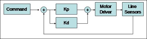
LINE CONTROL VARIABLE FUNCTION 

Purpose: Update line sensors' analog variables

Inputs:

       LineGainsT Gains: Structure containing speed, KP, and KD values.

void LineControl(LineGainsT Gains)

{

       read line sensor value, LineL, scale by 1000 and the calibration value, and save as LineL

       read line sensor value, LineL, scale by 1000 and the calibration value, and save as LineM

       read line sensor value, LineL, scale by 1000 and the calibration value, and save as LineR


       if LineL is less than LINE_SENSOR_CUTOFF, set bLineL

       if LineM is less than LINE_SENSOR_CUTOFF, set bLineM

       if LineR is less than LINE_SENSOR_CUTOFF, set bLineR


       save errorlast from error

       update new error value

       update command 1 to average speed

       find the proportional command and scale by KP

       find the derivative command and scale by KD

       add proportional and derivative command signals and save as command2

       if savederror is greater than zero

       {

              if error is greater than the absolute value of saved error, update error with the new max

       }

       if saved error is less than zero

       {

              if error is greater than the absolute value of saved error, update error with the new max

       }

       if the line sensors are off, on, and off the line(respectively), reset savederror

       if the current state is one of several control-driven states

       {

              drive according to the linecontrol command signals

       }

}


TIMER OVERFLOW INTERRUPT FUNCTION 

Purpose: Increment timer 0/channel 2's overflow number and set overflow time

void interrupt _Vec_tim0ovf Timer0OverflowHandler(void)

{

       Reset the overflow flag

       increment overflow count

       convert overflow count to a usable form.

}


TIMER 0/CHANNEL 4 INTERRUPT HANDLER FUNCTION 

Purpose: Handle timer 0's channel 4 interrupt features:

clear timer flag 4, handle overflow with timer flag 2, update

beacon 4's period and duty cycle

void interrupt _Vec_tim0ch4 Timer0Ch4InterruptHandler(void)

{

       declare unsigned long dt

       reset Timer 4 flag

       if overflow flag is set

       {

              reset overflow flag

              increment overflow coutn

              convert overflow count to a usable form.

       }

       if Beacon4In is nonzero

       {

              save periodlast

              update period

       }

       otherwise

       {

              update onperiod

              determine the the period and save as dt

              if dt is within 25% of the actual duty cycle of the beacons

              {

                     update duty, scaled by 100

              }

              otherwise

              {

                     reset duty to 0

                     reset DutyGoodCount

              }

       }

}


TIMER 0/CHANNEL 5 INTERRUPT HANDLER FUNCTION 

Purpose: Handle timer 0's channel 5 interrupt features:

void interrupt _Vec_tim0ch5 Timer0Ch5InterruptHandler(void)

{

       clear the timer 5 flag

       set StartFlash

       disable Timer5 interrupts

}


TIMER 0/CHANNEL 6 INTERRUPT HANDLER FUNCTION 

Purpose: Handle timer 0's channel 6 interrupt features:

clear timer flag 6, handle overflow with timer flag 2, update

beacon 6's period and duty cycle

void interrupt _Vec_tim0ch6 Timer0Ch6InterruptHandler(void)

{

       declare unsigned long dt  

       reset Timer 6 flag

       if overflow flag is set

       {

              reset overflow flag

              increment overflow coutn

              convert overflow count to a usable form.

       }

       if Beacon6In is zero

       {

              save periodlast

              update period

       }

       otherwise

       {

              update onperiod

              calculate period

              if dt is within 25% of the specified beacon frequency

              {

                     update duty as a percentage of ontime/period

              }

              otherwise

              {

                     reset duty

                     reset dutygoodcount

              }

       }

}


TIMER 0/CHANNEL 7 INTERRUPT HANDLER FUNCTION 

Purpose: Handle timer 0's channel 7 interrupt features:

clear timer flag 7, handle overflow with timer flag 2, update

beacon 7's period and duty cycle

void interrupt _Vec_tim0ch7 Timer0Ch7InterruptHandler(void)

{

       declare unsigned long dt

       clear timer 7 flag

       if overflow flag is set

       {

              reset overflow flag

              increment overflow coutn

              convert overflow count to a usable form.

       }

       if beacon7in is zero

       {

              save periodlast

              update period

       }

       otherwise

       {

              update onperiod

              calculate dt as the total period

              if dt is within 25% of specified period

              {

                      update duty as percentage of onperiod/period

              }

              otherwise

              {

                     clear duty

                     clear dutygoodcount

              }

       }

}


TIMER 1/CHANNEL 7 INTERRUPT HANDLER FUNCTION 

Purpose: Handle timer 1's channel 7 interrupt features:

clear timer flag 7, update current time by 2.4 ms clock pulse, update

timer 1/channel 7's current time, update beacon 4's period and duty cycle

void interrupt _Vec_tim1ch7 Timer1Ch7InterruptHandler(void)

{

       declare static unsigned long Millisecondsx10.

       increment Millisecondsx10 by 24

       calculate actual time

       clear timer7 flag

       calculate new output compare time

       enable interrupts

       update beacon information for beacon 4

       update beacon information for beacon 6

       update beacon information for beacon 7

       run LineControl()

}


Drive() function

Purpose: Move the drive motors in particular configurations

Inputs:

       DriveType: enumerated type for selecting the drive configuration

       Direction: enumerated type for selecting motor directions

       SpeedAverage: average speed added to both motors

       SpeedDifference: differential speed added to one motor and subtracted from the other.

void Drive(DriveTypeT DriveType, DirectionT Direction, int SpeedAverage, int SpeedDifference)

{

       if the drive type is anything but DriveLineFollow

       {

              if SpeedAverage is greater than 100, peg it at 100.

              if SpeedAverage is less than zero, peg it at 0.

       }

       switch depending on DriveType

       {

              case DriveLineFollow:

              {

                     declare ints A and B

                     Calculate A by adding SpeedAverage and SpeedDifference

                     Calculate B by subtracting SpeedDifference from SpeedAverage

                     if A is less than -100, peg it at 100.

                     if A is greater than 100, peg it at 100.

                     if B is less than -100, peg it at 100.

                     if B is greater than 100, peg it at 100.

                     if A is greater than or equal to 0

                     {

                           set duty cycle for PWMDTY0 and PWMDTY1

                     }

                     otherwise

                     {

                           negate A

                           set duty cycle for PWMDTY0 and PWMDTY1

                     }

                     if B is greater than or equal to 0

                     {

                           set duty cycle for PWMDTY2 and PWMDTY3

                     }

                     otherwise

                     {

                           negate B

                           set duty cycle for PWMDTY2 and PWMDTY3

                     }

              }

              case DriveRotate:

              {

                     if direction is left

                     {

                           Set duty cycles

                     }

                     otherwise if direction is right

                     {

                           Set duty cycles

                     }

                     break;

              }

              case DriveTurn:

              {

                     if direction is left

                     {

                           Set duty cycles

                     }

                     otherwise if direction is right

                     {

                           Set duty cycles

                     }

              }

              case DriveTurnReverse:

              {

                     if direction is left

                     {

                           Set duty cycles

                     }

                     otherwise if direction is right

                     {

                           Set duty cycles

                     }

              }

              case DriveStraight:

              {

                     if direction is forward

                     {

                           Set duty cycles

                     }

                     otherwise if direction is reverse

                     {

                           Set duty cycles

                     }

              }

              case DriveStop:

              {

                     Set all duty cycles to 0

              }

              default:

              {

                     Set all duty cycles to 0

              }

       }

}


BEACON ORIENT FUNCTION 

Purpose: Perform rotational search to find a beacon given duty cycle parameters

Input: Rotational direction, beacon of interest, duty cycle of interest, duty cycle tolerance, beacon state

Output: Beacon state (1 for succesful beacon detection or no output)

int BeaconOrient(DirectionT Direction,BeaconT Beacon, unsigned int GoalDutyCycle, unsigned int Tolerance,unsigned char Reset)

{


       if reset

       {

              reset beaconstate

       }

       {

              switch on BeaconState

              {

                     case 0:

                     {

                           rotate left

                           if the beacon's average duty is within tolerance

                           {

                                  change to BeaconState 1

                                  stop motors

                           }

                           break

                     }

                     case 1:

                     {

                           break(do nothing)

                     }

                     default

                     {

                           break(do nothing)

                     }

              }

       }

       return BeaconState

}

BeaconCode.c

include files


 ******************************************** 

 ********** BEACON UPDATE FUNCTION **********

 ********************************************

 Purpose: Motor operation at set T0-T3 duty cycles

 Input: Beacon struct duty cycle-relevant variables

 Output: Beacon struct duty cycle-relevant variables

 ********************************************

BeaconT UpdateBeacon(BeaconT Beacon, unsigned long TimerOverFlow)

{

       declare int j for incrementing through array

       if the duty is greater than zero

       {

              if the beacon period is greater than 2times the beacon frequency,

              {

                     reset the duty to zero

                     reset the duty good counter to zero

              }

              otherwise, if the Duty is not between 0 and 100

              {

                     reset the duty to zero

                     reset the duty good counter to zero

              }

              otherwise

              {

                     increment the good count

              }

       }

       otherwise

       {

              set the good count to 0

       }

        if the good count is > 0

       {

              save the current duty into element i of thearray

              increment i

              save only the modulus of i

       }

       otherwise

       {

              for all the elements in the array

              {

                     clear the element.

              }

              reset i to 0

       }

if the goodcount is greater than the array size by 5(eliminating any bad startup periods)

       {

              reset the average to 0

              for all the elements in the array

              {

                     add the element to the average

              }

              scale the average by the number of elements

       }

       otherwise

       {

              set the average to 0

       }

       return the beacon data structure

}

DigitalIO.c

include files


InputT CreatePortEInput(E128Register BitMask)

{

       create variable Input of type InputT

       update the internal memory of Input with pointers for port E.

       set the bitmask for Input equal to BitMask

       Return Input

}

InputT CreatePortTInput(E128Register BitMask)

{

       return the result of InputConfig with pointers for port T and BitMask

}

InputT CreatePortMInput(E128Register BitMask)

{

       Return the result of InputConfig with pointers for port M and BitMask

}

InputT CreatePortADInput(E128Register BitMask)

{

       create variable Input of type InputT

       update the internal memory of Input with pointers for port AD.

       set the bitmask for Input equal to BitMask

       Return Input

}

OutputT CreatePortTOutput(E128Register BitMask)

{

       return the result of OutputConfig with pointers for port T and BitMask

}

OutputT CreatePortMOutput(E128Register BitMask)

{

       return the result of OutputConfig with pointers for port M and BitMask

}

OutputT CreatePortADOutput(E128Register BitMask)

{

       create variable Output of type OutputT

       update the internal memory of Output with pointers for port AD

       set output.bitmask equal to BitMask.

       Return Output

}

InputT InputConfig(E128Register *DirPort, E128Register *Port, E128Register BitMask)

{

       create variable Input of type InputT

       set internal variables equal to input variables

       modify the port's direction register with 0's in the bitmasked locations  

       return Input

}

OutputT OutputConfig(E128Register *DirPort, E128Register *Port, E128Register BitMask)

{

       create variable Output of type OutputT

       set internal variables equal to input variables

       modify the port's direction register with 1's in the bitmasked locations  

       return Output

}

E128Register InputRead(InputT Input)

{

       return the data register bitmasked with Input.BitMask

}

E128Register OutputRead(OutputT Output)

{

       return the data register bitmasked with Output.BitMask

}

void OutputWrite(OutputT Output, E128Register Value)

{

       create temporary variables a and b of type E128Register

       set a equal to the bits we want to change

       set b equal to the bits we don't want to change

       bitwise-or a and b together and set the data register equal to that value.

}

HardwareInit.c

include files


void InitTimer0(void)

{

Input Capture/Output Compare (1=output compare)

Set all Timers for Input Capture

Enable the timer subsystem

Output Compare Action (00=nothing 0L=toggle M0=clear ML=set)           

Input Capture Action (00=disabled 0A=rising B0=falling BA=any edge)

Configure all inputs for any edge

enable interrupts for timer 4, 5, 6, and 7.

enable the overflow interrupt

}

void InitTimer1(void)

{

Input Capture/Output Compare (1=output compare)

set timer 7 for output compare

Enable the timer subsystem

Output Compare Action (00=nothing 0L=toggle M0=clear ML=set)           

set timer 7 to toggle

Input Capture Action (00=disabled 0A=rising B0=falling BA=any edge)

disable all input capture actions

enable interrupts for timer 4, 5, and 6.

initialize first timer value for TIM1_TC7

}


void InitPWM(void)

{

Enable PWM channel 0, 1, 2, 3, 4, 5

Set PWM Polarity Register

Set PWM Clock register

Set PWM Prescaler register to (bus clock/2)

disable center align               

set bits in the control register               

Scale clock SA

Scale clock SB

Set the PWM period registers.

initialize the duty cycle registers to zero

Link PWM channel 0 to the T0 pin.

}


[1] Sun Tsu.  The Art of War. 

[2] Fairchild Semiconductor: Phototransistor/Reflective Object Sensor QRB1133/QRB1134, www.fairchildsemi.com