Electrical
List of Electrical Components:
E128 Microcontroller:An E128 microcontroller board was used to handle all the sensory inputs and generate all the output signals for the robot. The E128 pin out is shown below:
7.2 V Batteries:Two 7.2 V batteries with a common ground were used to supply power to the robot. A switch and a 5A fuse were placed in series with the ground wire to turn the robot on and off, and as a safety precaution. One battery was used to power the two drive motors. The other was used to power the E128, sensor circuits, and the drawbridge motor of the robot. The sensor circuits required a 5 V power supply, so the battery was first sent through a voltage regulator.5V Voltage Regulator:
 A voltage regulator provided a 5 V fixed voltage supply from the 7.2 V batteries to the robot's sensor circuits. To ensure that the voltage regulator remained within its operating temperature, the following calculation was performed: Maximum current rating, Imax = 1 A Junction to ambient thermal resistance, qJ-A = 60 °C/W (no heat sink) Maximum junction temperature, TJ = 125 °C Power dissipated, P = VI = (7.2 V - 5 V)(1 A) = 2.2 W Junction temperature, TJ = (2.2 W) (60 °C/W) - 25 °C = 107 °C < 125 °C A heat sink was used to further guarantee that the voltage regulator would remain within its operating temperature. Drive Motors:
 DC motors were used to turn the wheels of the robot. Each motor was driven using a TLE 5206 driver kit in drive-brake mode with PWM and digital output signals from the E128. A PWM signal frequency of 100 Hz was used, and determined as follows: Motor mechanical time constant, tmotor = 19 ms Operate motor at PWM frequency, f > 1 / tmotor = 1 / 19 ms = 52.6 Hz Use PWM frequency, f = 100 Hz Flash Sensor:
 An IR phototransistor was used in series with a resistor to detect the flash at the start of the game. The high side of the resistor was connected to a digital input pin on the E128. A 47 kΩ resistor was selected after testing with different sizes to ensure that a 5 V signal would be generated in the presence of a flash. IR Beacon Sensor:
 To sense the 50% IR beacon above the ball dispenser, the above circuit was used. The circuit has the following stages: (a) Virtual ground circuit: A virtual ground of 2.5 V was generated using an op-amp in a buffer configuration so as to provide a 2.5 V line that draws no current. (b) Trans-resistive circuit: An IR phototransistor was used with an op-amp in negative feedback to obtain a signal that was linearly proportional to the detected IR signal. The 3.3 kΩ resistor in negative feedback was sized so that when the robot was in the starting box, the 50% IR beacon signal at the ball dispenser was amplified enough to be visible, and at the same time, not saturate the op-amp when seeing the 30% IR beacon signal at goal 1. Capacitors were added to remove noise from the detected IR signal. (c) High pass RC filter: A high pass RC filter was used to cancel out the effects of ambient light. The signal out of the filter was centered at the virtual ground with sharp peaks and valleys at the rising and falling edges of the IR signal. The corner frequency was determined as follows: Rise time of signal out of trans-resistive circuit = 5 ms fc,max = 1 / 5 ms = 200 kHz Choose R4 = 1 kΩ, C3 = 1 nF fc = 1 / 2pR4C3 = 1 / 2p(1 kΩ)(1 nF) = 159 kHz (d) Inverting amplification circuit: While the high pass filter removed the effects of ambient light, the signal was also attenuated. An amplification stage with an op-amp in negative feedback was used to strengthen the signal. (e) Comparator circuit with hysteresis: Finally, the signal consisting of peaks and valleys at the rising and falling edges of the IR signal was converted into digital signal using a comparator. The reference voltage was set to the virtual ground. Hysteresis band calculations are shown below: Vs = 5 V Vref = 2.47 V R9 = 2.2 kΩ R10 = 100 kΩ R11 = 3.3 kΩ Vref1 = (Vs - Vs)(R9/(R9 + R10 + R11)) + Vref = (5 - 2.47)(2.2/(2.2 + 100 + 3.3)) + 2.47 = 2.52 V Vref2 = (R10/(R9 + R10))(Vref) = (100/(2.2 + 100))(2.47) = 2.42 V This signal was sent to digital input pins on the E128 to calculate the signal's duty cycle. Note that since the signal was inverted three times (trans-resistive circuit, inverting amplifier and comparator), the final output had a duty cycle of (100 - IR beacon signal duty cycle). A final adjustment was made in software to obtain the actual duty cycle of the IR beacon signal. Tape Sensors:
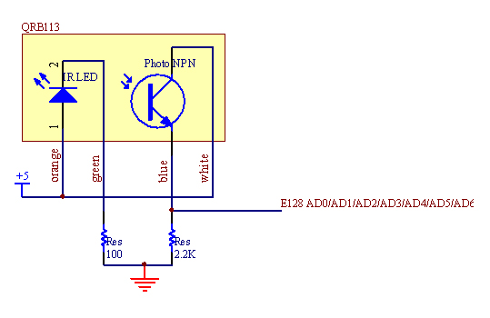 Seven tape sensors were used by the robot to detect and follow the tape on the field. The tape sensors consist of an IR LED and IR phototransistor next to each other. The circuit for the LED part of the tape sensor consisted of an LED in series with a resistor to limit the current to the LED. The value was calculated using the LED's maximum forward voltage drop and the forward current value at that condition. Vf = 1.7 V at If = 40 mA R = V / I = 1.7 V / 40 mA = 82.5 Ω Finding the minimum resistor value to be 82.5 Ω, a 100 Ω resistor was chosen. The circuit for the phototransistor part of the tape sensor consisted of the phototransistor in series with a resistor. Changes in intensity of the reflected IR signal seen by the phototransistor correspond to changes in current flowing through the circuit. Therefore, the voltage on the high side resistor changes when the tape sensor is over the white floor or the different-colored tapes. Different resistor values were tested with to obtain distinct voltage readings from when the tape sensor was over the white floor or the different-colored tapes, and a 2.2 kΩ resistor was selected. The voltage was read by A/D ports on the E128. Drawbridge Motor:
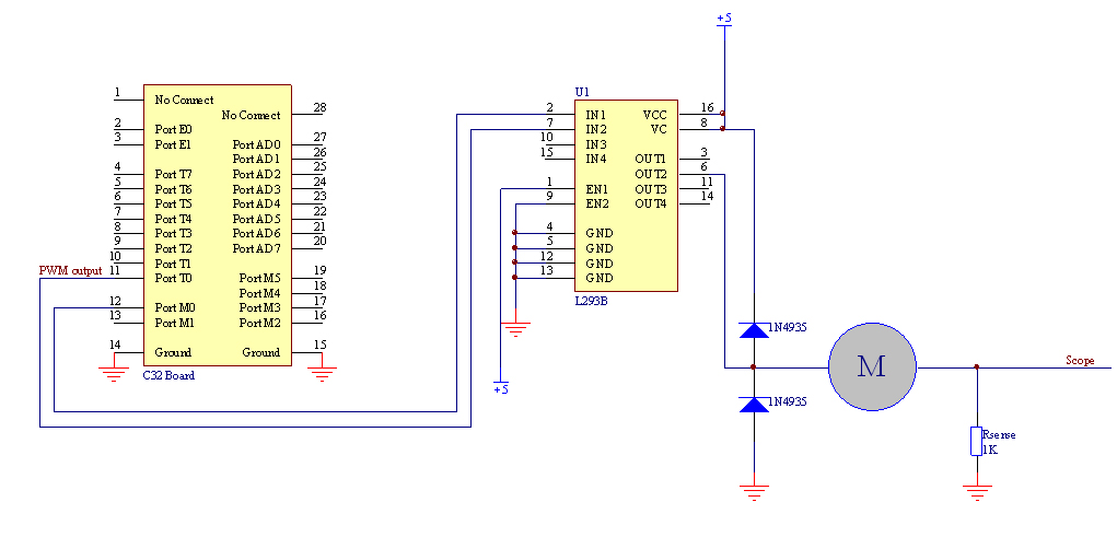
 The drawbridge that dispensed the collected balls into goal 3 was actuated by a DC motor that wound and unwound a length of fishing wire. The drawbridge motor was powered directly by a 7.2 V battery. The motor was driven using a L293B driver in drive-brake mode with PWM digital output signals from the E128. To determine what PWM frequency to use, the following experimental procedure and calculations were performed:
Maximum L293B current = 1 A / channel Imax = V / Rcoil = 5 V / 7.07 Ω = 0.707A < 1 A Drawbridge Motor Stop Switch:
 A contact switch was used to determine when to stop the drawbridge motor when the drawbridge was raised up all the way. The high side of the resistor was connected to a digital input pin on the E128. When the drawbridge is up, the switch is closed, and a high signal is sent to the E128. |