
► Schematic diagram of the
circuit
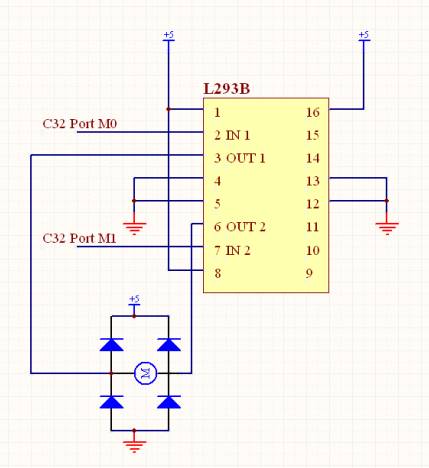
►
Design calculation
The
measured resistance of door lock motor was about 2 ohm. Therefore, supplying 5V, the current becomes
5v/2ohm= 2.5A. Regarding that the peak output current of L293B is 2A, the
current flowing inside the motor is slightly over 2A, but it does not occur any
problem because the motor will be used just for several seconds. Voltage
regulator (LM7805) was used to regulate the voltage from 14V to 5V. 7805’s peak
output current is 2.5A when the voltage difference between the input and the
output is 9V (14-5=9V). Therefore 7805 can supply enough current for door lock
motor.