Electrical
List of Electrical Components:Watercraft HelmDesign Calculations:Design Calculations for all Electronics: .htm, .doc(includes required 8 hour battery life calculation) Connection Block Diagrams: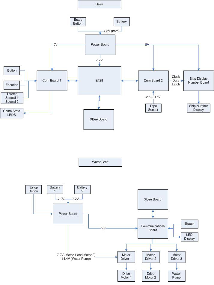
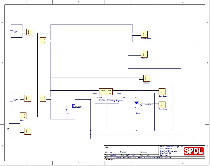
Watercraft Power Board:The purpose of this circuit board was to provide the following power outputs from two rechargeable NiCad Battery packs, each supplying a nominal voltage of 7.2V:
Watercraft Communications Board:This circuit board houses the two motor drive PICs and acts as a junction point for all the ancillary electrical components and circuit boards on the watercraft.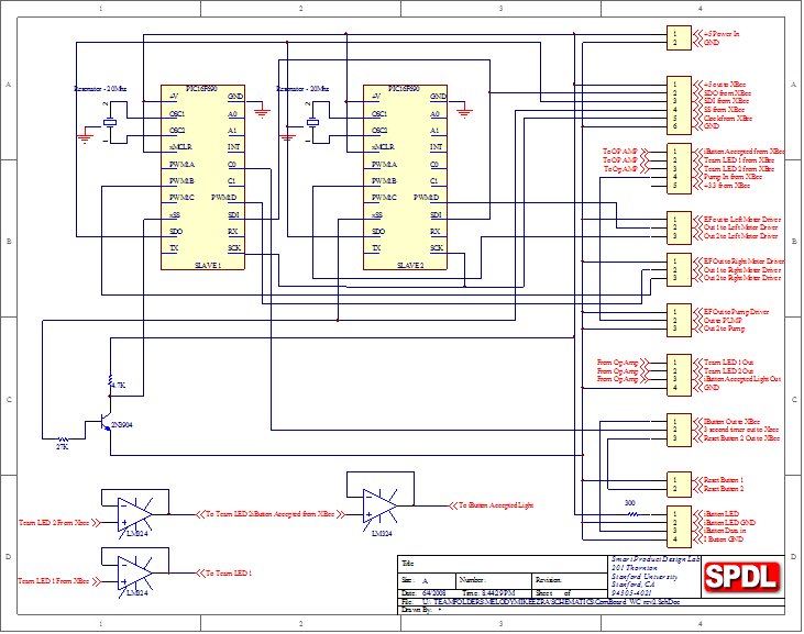
Watercraft XBee Board + Additions:The watercraft XBee board was assembled according to the directions provided by the class. It houses the XBee transmitter/receiver chip, and the BoatXBee PIC. The XBee Additions are the additional components that were added to the XBee boards which were issued at the beginning of the project.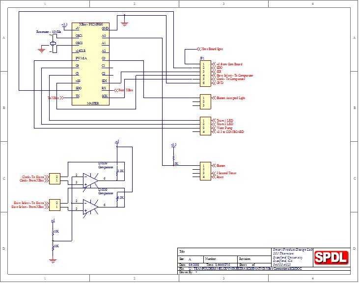
Helm Power Board:The purpose of this circuit board was to provide the following power outputs from one rechargeable NiCad Battery pack, supplying a nominal voltage of 7.2V: 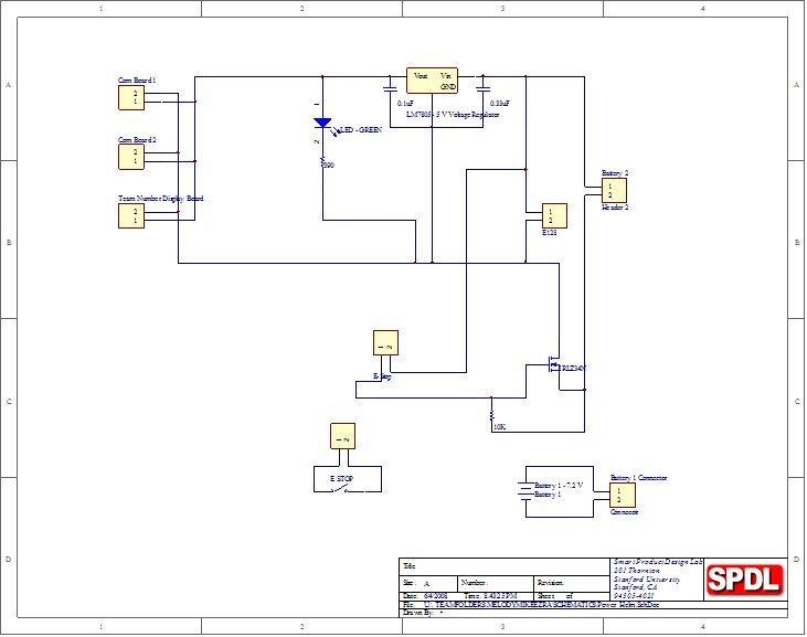
Helm Communications Board #1:The purpose of the Communications Board 1 was to provide input / output connections for the following inputs and outputs that were associated with the 24 pin connector on the E128:
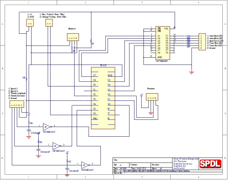
Helm Communications Board #2:The purpose of the Communications Board 2 was to provide input / output connections for the following inputs and outputs that were associated with the 20 pin connector on the E128:
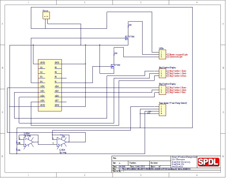
Ship Number Display Board:The Ship Number Display Board was built to drive the 2 digit 7 segment LED displays for showing the Craft Number currently linked to the helm. The seven segment LEDs require a considerable amount of overhead to make them work so the circuitry was moved to its own circuit board.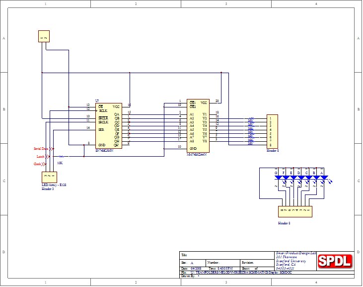
|