Helm Electronics
Helm Power Consumption
To fulfill the project specification of the Helm having sufficient battery capacity for 8 hours of continuous operation, we measured the current through the battery’s leads (one 7.2 V NiCad battery rated at 1900 mA-hr) for 10 minutes and measured its average current to be roughly 49 mA.
This gives us a theoretical operating time of 1900mA*Hr / 49mA = 38.8 hours which is well above the 8 hour requirement outlined in the specifications.
Accelerometer Circuit
The accelerometer required 3.3 V to operate, which was provided by a LP2950 low dropout voltage regulator, as shown in the Figure 1 below.
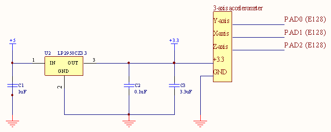
Figure 1: Accelerometer schematic
Flex Sensor Circuit
To output a voltage from the flex sensor to be used as the input to an A/D pin on the E128, we implemented an electrical circuit using an operational amplifier as shown below in Figure 2. We empirically confirmed the flex sensor’s specifications: a bend angle of 0° resulted in a resistance of roughly 10 kΩ while a bend angle of 90° resulted in roughly 35 kΩ. To provide a linear output, we implemented a non-inverting amplification circuit using a LM324 operational amplifier with a non-inverting input voltage of roughly 0.71 V, which was found by trial and error. Despite some problems with drift in the output, the circuit provided excellent voltage output.
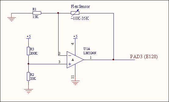
Figure 2: Flex sensor schematic
Special Actions Circuit
To provide two special actions for the watercrafts, we implemented two momentary switches on our Helm. The schematic for these momentary switches is shown below in Figure 3. When each switch was pushed, the micro-controller pin’s value would read +5 since the pin then coincides with +5. When each switch is not pushed, the micro-controller pin’s value would read 0 since there is no current through the resistor. These situations are ideal; however, the minimum input high voltage for the E128 is 0.65VDD5 or 3.25 V, which is 1.75 V below the ideal +5. In other words, when a switch is pushed, even a voltage such as 4.8 V (usually 4.95 V was observed) would set a logic HI.
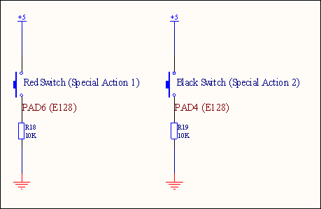
Figure 3: Momentary switches schematic
Helm Display Circuit
To show the helmsperson the current state of an engagement, we placed five LEDs on the Helm: a set of small green, yellow, and red LEDs to describe the engagement status, and large blue and red LEDs to show the team affiliation and active goal. We placed a relatively standard 3.3-kΩ resistor in series with each of these five LEDs. In addition, we placed a double-digit 7-segment LED display on the Helm. We placed a 220-Ω resistor in series with each of the double-digit 7-segment LED display’s LEDs to have a fairly high current for brightness purposes. Each of the LEDs has a forward voltage drop of 2.0 V. In addition to our added resistors, the E128 protection board has a 1k series resistance per pin. Thus, our calculated current through the 7-segment LEDs was 2.5mA. The calculated current through the five display LEDs was .7mA. This was enough current to see the LEDs but keep power consumption very low.
The double-digit 7-segment LED display is common anode (one anode per digit). Digit 2 is considered to be the digit next to the decimal point while Digit 1 is considered to be the digit in the tens place. See Figures 4 and 5 for schematics of the gameplay LEDs and the double-digit 7-segment LED display.
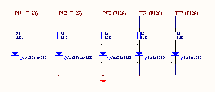
Figure 4: Gameplay LEDs schematic
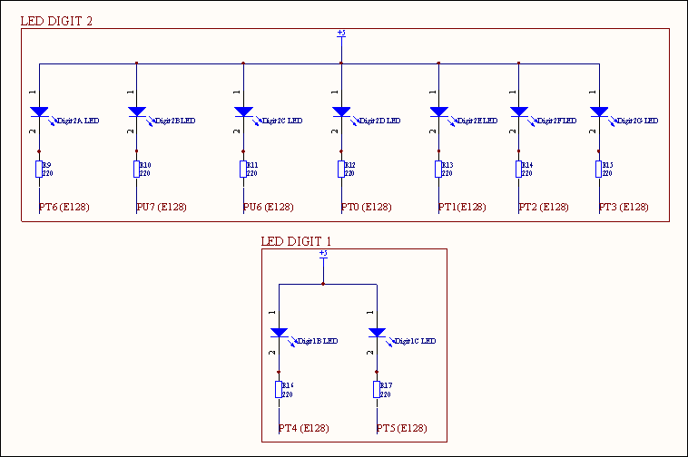
Figure 5: Double-digit 7-segment LED display schematic
Craft Electronics
Main PIC Circuit
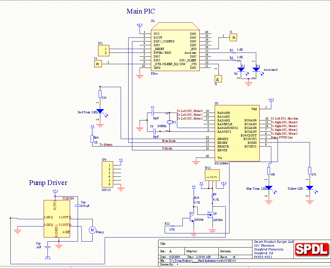
The Main PIC communicates with the XBee board and controls the pump unidirectionally through PWM, which is level-shifted to 5V. The Pump draws up to 2.5A, which can easily be supplied by the TLE H-Bridge. It gives commands to the Left and Right PIC’s through eight individual I/O lines connected directly to these PIC’s. Four lines per PIC give 3-bit speed resolution and one direction bit. While this method uses a large number of I/O, we had sufficient ports available and it is simple to implement and troubleshoot. The Main PIC also controls three LED’s: Red, Blue and Yellow. The resistors were sized by experimentally measuring the current at which the LED stops growing brighter and then calibrating this current (and the LED drop-off voltage) for the 3.3V PIC.
The Red LED had Vf = 1.7V and I = 10.7mA. R = (3.3V-1.7V)/10.7 = 150 Ohms
The Blue LED had Vf = 2.8V and I = 4.1mA. R = (3.3V-2.8V)/4.1 = 122 which is rounded to 130 Ohms.
The Yellow LED had Vf = 1.9V and I = 11.9mA. R = (3.3V-1.9V)/11.9 = 120 Ohms.
Note also that all of these currents can easily be supplied by the PIC, so no transistors are necessary.
Secondary PIC Circuits
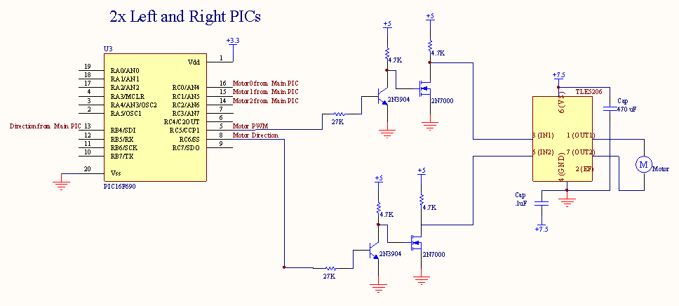
The Left and Right PICs have four input lines from the Main PIC and each drive one of the main drive motors bidirectionally. Both the PWM and direction lines are level-shifted to 5V to better work with the TLE H-Bridge driver.
The motors draw roughly 4.5A stall current at 5V, which is below the 6A maximum for the TLE 5206-2. Also, when tested in water, they drew 1.7A continuous which is well below the 5A maximum for the driver.
