Frame & Structure top
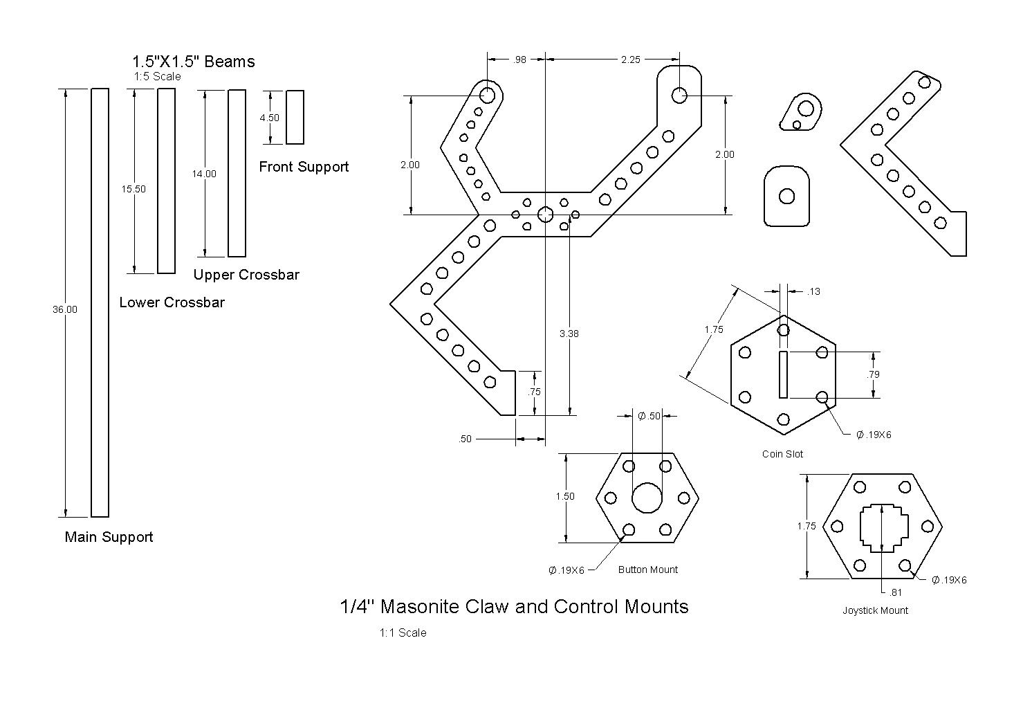
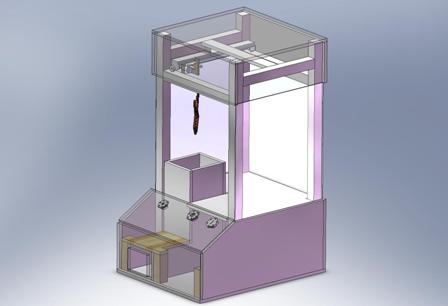
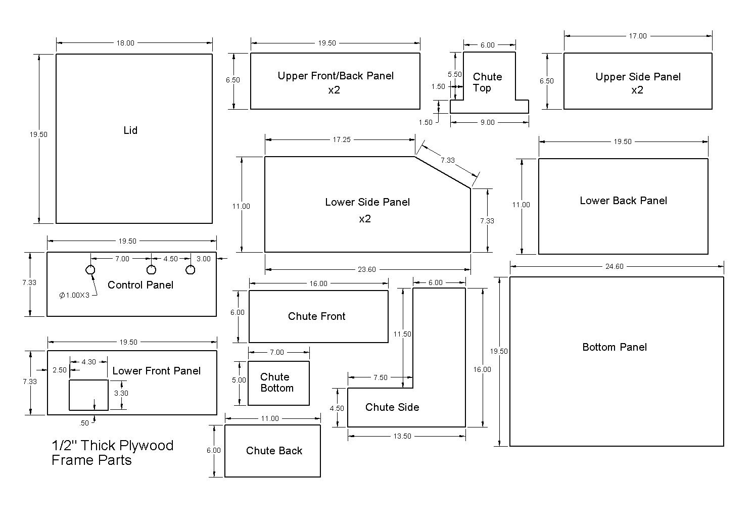
In designing The Swag Factory, we wanted a reliable and durable structure that could survive transportation and any accidents in the course of development. Given the budget and time constraints and the good availability of the necessary tools, we chose a frame built of wood and assembled with standard steel wood screws. The paneling was entirely constructed from ½” thick plywood while the support columns and braces were made from 1½” x 1½” beams. Steel L-Brackets were added where additional strength was necessary or where other bracing was impossible for the panels. The joystick, drop button, and coin slot mounts required more complex geometry with tighter tolerances and were fabricated from ¼” thick Masonite using a LaserCAM. Below are dimensioned drawings of the components of The Swag Factory’s frame and structure: (Click on any dimensioned drawing to see a larger version of the image.)
2D Positioning Mechanism top
In creating the 2D positioning mechanism for The Swag Factory, we were determined to use two surplus inkjet printers one of our group members had been planning to junk. Upon dissecting the printers, we discovered that it was possible to surgically remove the DC Motor-powered, belt-driven inkjet positioning mechanisms without damaging them. Each proved to be a quick, reasonably powerful, low friction means of providing linear motion.
In coupling the two to provide 2D positioning, we made certain to avoid awkward moments by centrally mounting the second drive to the first. To further reduce the risk of binding in the upper drive, we provided the second, lower drive with its own support through bearings on wooden rails. Limit switches were placed at the extremes of the range of motion allowing simple and full user control without risk of damaging the drives. Proper wire routing was essential to avoid hang-ups.
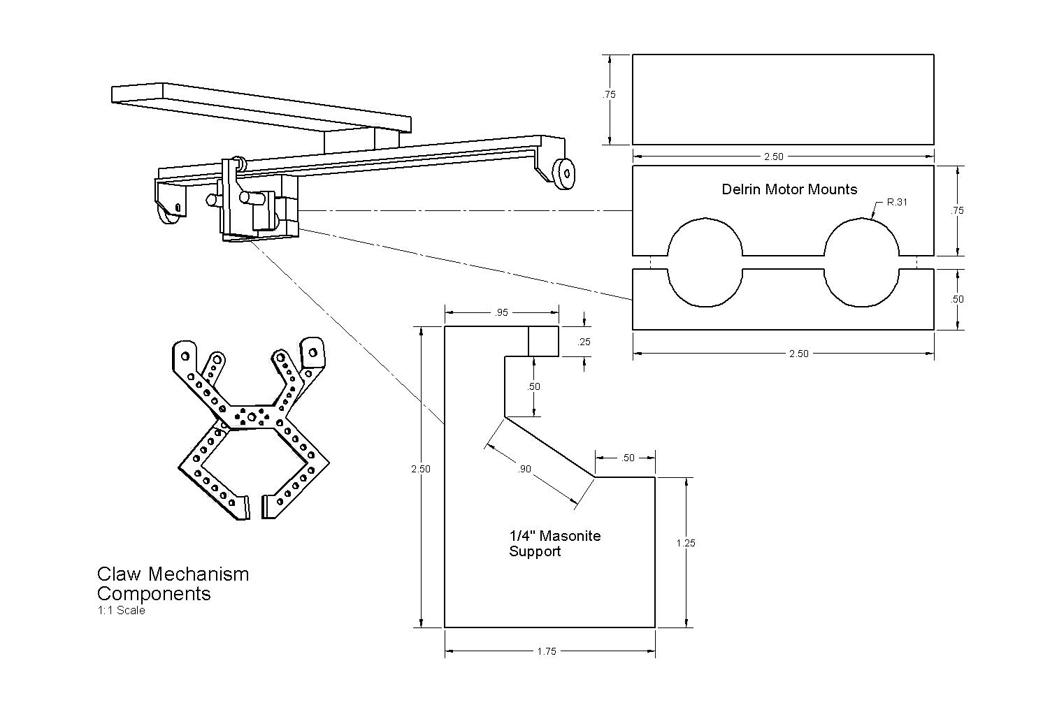
Claw Mechanism top
Because any heavy load would have placed a strain on our scavenged 2D positioning
system, we needed to design the claw and claw mechanism to be light. After
some simple speed calculations, we selected low-cost, plastic geared and
plastic housed DC motors that would be sure to provide optimum lift for
any swag the user might catch. The motor mounts were fashioned after a simple
and proven design, but the slippery nature of the mount’s and motors’ material
required hot glue be applied for a secure hold. The windings were originally
intended to be the threaded section of steel bolts drawing steel cable,
but this was overweight, disagreeable to work with, and excessive for lifting
swag. Simple dowel sections with wool thread served very well for the application.
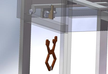
Because the lower printer driver only provided support to its slide at the
shaft, the entire lifting mechanism was prone to rotation when loaded. To
counter this, we added a central support member equipped with a bearing
that ran in a convenient track in the printer driver above the mechanism.
This support member also provided an excellent location for the limit switches
that allowed detection of the claw’s critical states via switch-mounted
guides for the two lift strings and balls glued onto the lift strings.
The claw itself was designed for maximum simplicity, ease of fabrication,
and reliability. It was fabricated from a number of bonded ¼” thick Masonite
parts cut on a LaserCAM. By using two lift strings, we had the necessary
position and open/close state control over the claw without needing to add
actuators to the claw itself. When drawn in, one string would pull the claw
open and lift it when its open limit was reached, and the other string did
the same for closing the claw. When the strings’ relative tension was controlled
using the above mentioned limit switch system, the claw could be opened
and closed as necessary either in the swag or above the prize chute.