Tape
Sensors
Based on our lab 8
experience, we decided that 3 tape sensors would give us all of the control we
needed to maneuver quickly and accurately.
We mounted 2 sensors on the front, separated by the width of the tape. With these sensors, we could follow the tape
line actively, by increasing the speed of one of the motors every time one of
the sensors saw tape. This algorithm
depends on starting centered on the line, so we added a third sensor in the center
of the ‘bot, directly on the wheel axis. With this, we could rotate in place around
the center sensor, which gave us a very fast way to get on the line and orient
correctly to begin line following.
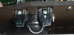
 Originally,
we started with a circuit that took the output from the phototransistor side of
the tape sensor and passed it into a 74HC14 (Schmitt
Originally,
we started with a circuit that took the output from the phototransistor side of
the tape sensor and passed it into a 74HC14 (Schmitt
trigger
with hysteresis). We realized later that
the output voltage was not reliably going above the built in thresholds of the
HC14 chip. To fix this, we changed from
an
HC14 to an LM339 comparator which allows the user to
tune the comparison voltage and hysteresis band. Knowing that
we didn’t need to worry about seeing red or
green
tape for our strategy, we decided to set the comparison value around 1V, with a relatively tight hysteresis
band. When we were testing the output
from the
phototransistors, we saw values 400-700mV while looking at a white surface and 1.8-3V when
we were on the tape, which gave us a pretty comfortable margin of
safety
for avoiding false positives and missing tape edges. To leave some margin for tuning, we created
the comparison voltage with a 10K resistor and a 20K pot,
which
allows for a range of comparison voltages from 0 to 3.33V (10/3). The 100K feedback resistor and 3.3K pull-up
were straight from the class notes (we left
the
100K because we don’t really care about the size of the hysteresis band).
|
Center
Tape Sensor |
Left Tape
Sensor |
Right
Tape Sensor |
|
|
|
|