Chassis
The
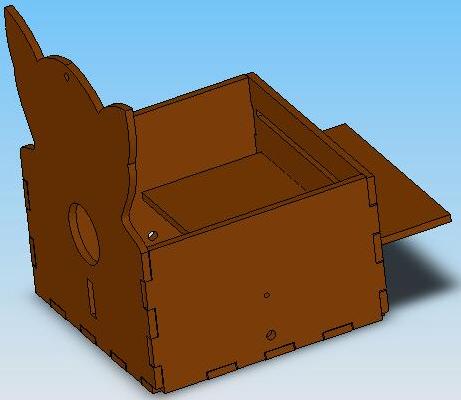
chassis of the robot contains and organizes the other components of the robot.
It was constructed out of laserCAM cut masonite. The tabs on the edges of
the panels keep all the panels in place and support the sides of the chassis.
The front panel of the chassis features openings for the ball dispenser, front
contact switch, and beacon detector. The side walls have holes for the ball
bearings used to support the wheel axels. The bottom has openings for the
tape sensors and casters. The back panel has slots for supporting the removable
tier. The removable tier organizes the contents of the robot. Since the tier
is removable, parts that were stored in the lower compartment could still
be easily accessed after assembly.
primarily used to find lines. Once the robot spotted a line on the center
sensor, it turned in place until the front sensors straddled the line. The
front sensors were also used in line following and detecting
the end of the line. All sensors were calibrated to see both green and black
tape.
The rectangular hole in the front of the chassis was for mounting a contact switch. This switch detected when the robot was close enough to Goal 3 to drop balls into it.