Actuators
Flippers
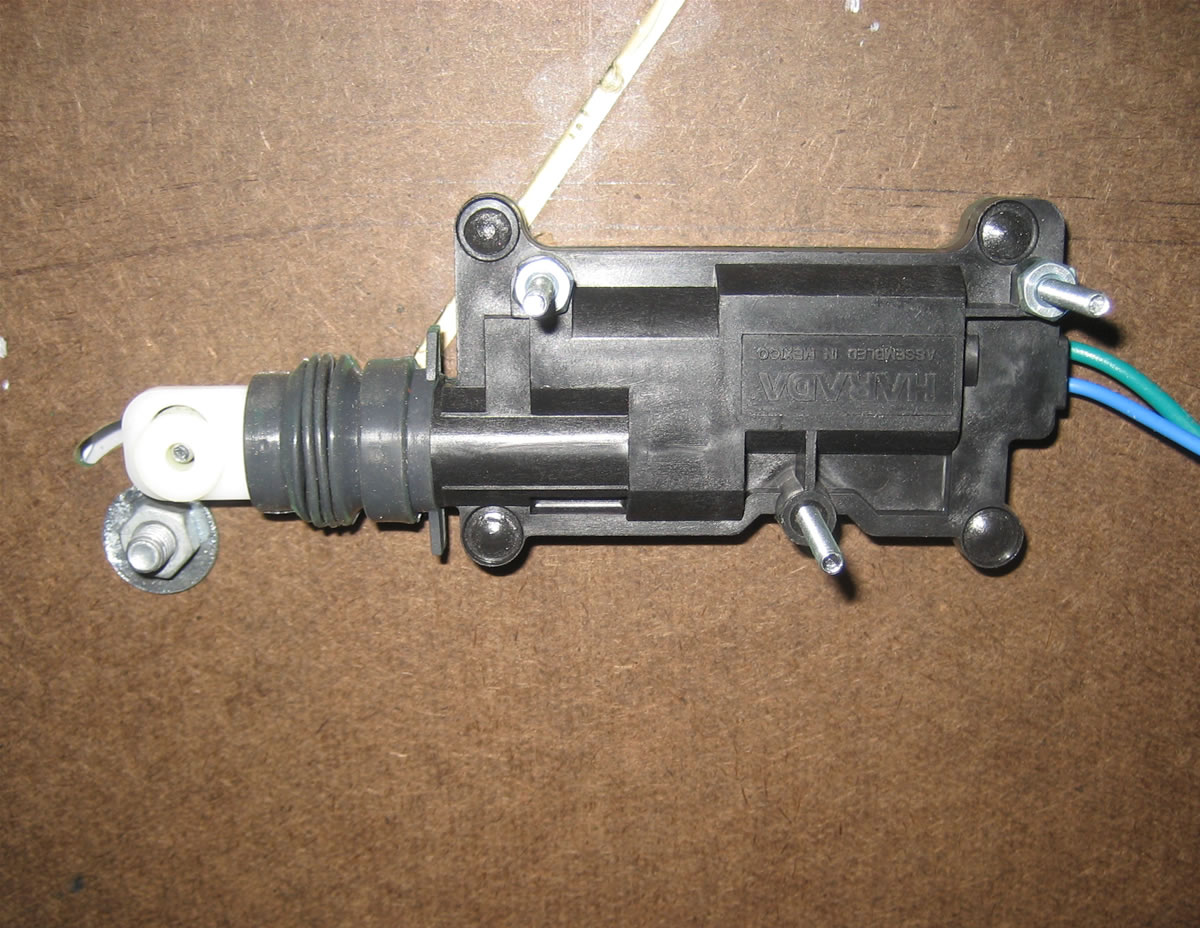
Because of the power restrictions, our design options for the flippers were limited. Normally, pinball machines use linear solenoids, which at 12 V and 3 A are pathetic. On the other hand, DC, servo or stepper motors would be challenging to use. In order to achieve adequate speed, power and mechanical robustness, we opted to use linear door-lock motors to push and pull off-axis from the flipper pivot.
The flipper design is just fast and strong enough for a well-timed swing, so rather than testing our luck using return springs, we chose to operate each flipper motor in a push-pull configuration, utilizing a bidirectional H-bridge. We operate the motor at full voltage for a predetermined time in each direction, which was based on the minimum complete travel time. In order to prevent blocking code, we utilize timers in the TMRS12 module.
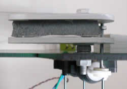
Each flipper is constructed from a piece of ½"foam core sandwiched between two identical laser-cut ¼" acrylic pieces, and bound together with glorious hot glue. The main pivot is constructed from a bolt with a smooth shaft section, locked to the playing surface between nuts and metal washers. Nylon washers prevent the acrylic from binding to the components on the bolt. With more time and better resources, we would have preferred to use a true shoulder screw to better control the tolerance stack, however for our purposes this design was more than adequate.
In order to make the playing surface removable for easier construction, debugging, etc., and to control the tolerances of the flipper-motor assembly, we mounted the motors directly to the underside of the playing surface and cut the features for the motors in the same pass/process as for the flippers. The layout of the playing surface and the flipper mounting holes can be seen here.
We achieved the realistic arcade-pinball experience by purchasing arcade buttons and maintaining the true electromechanical operation one expects when playing pinball. A mechanical-only system just wouldn't cut it.
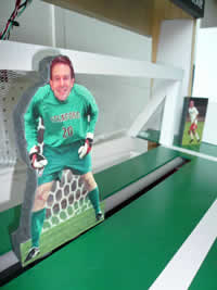
Goalie
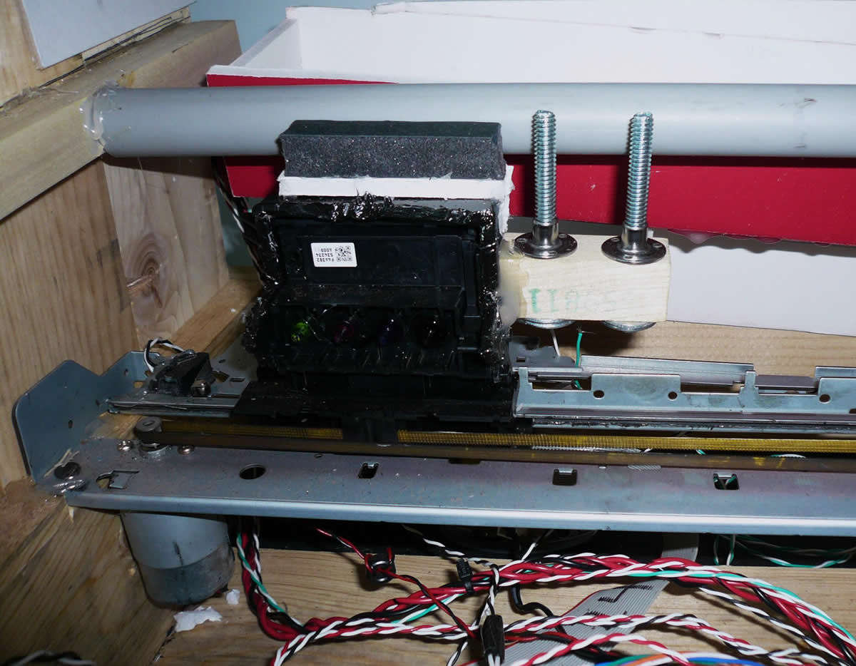
We felt that standard pinball games using stationary scoring targets and obstacles leave something to be desired, and so we created a moving goalie that travels across the front of the goal. By harvesting a free printer from the dump (woohoo free stuff!), we were able to get a robust linear actuation platform with a relatively simple interface, of the right size, speed and power for our project. After isolating the cartridge position drive train and motor from the rest of the system, we attached a removable Matt Ohline goalie for, you know, a personal touch. Don't mess with Ohline. The removability was necessary to securely mount the heavy drive train to the frame, while maintaining our modular playing field. Behind the goalie, we used a PVC pipe as a low-friction support so that a ball-strike wouldn't stress the drive train.
Like the flipper motors, the goalie motor is connected to a bidirectional H-bridge circuit, whose enable voltage comes from the PWM channel of the C32. At the beginning of the game, the duty cycle is set based on the difficulty level potentiometer, and so the game difficulty is defined by the speed of the goalie. The goalie communicates his position to the C32 via limit switches at either end of the travel. When a limit switch hits, the controller changes the goalie direction in software.
In a stroke of genius, we realized that we could turn the game into a single- or multi-player game by adding another goalie direction change switch in parallel with the limit switches, without any change to the hardware or software of the rest of the system. The user-goalie feature adds a great interaction to the game, but unfortunately also makes the game nearly impossible to beat (oops!). On the plus side we raked in quite a collection of pennies during the demonstration party, while dispensing only 2 prizes.
Diagram of both Goalie and Prize motor circuits being driven off of a single H-Bridge.
SWAG
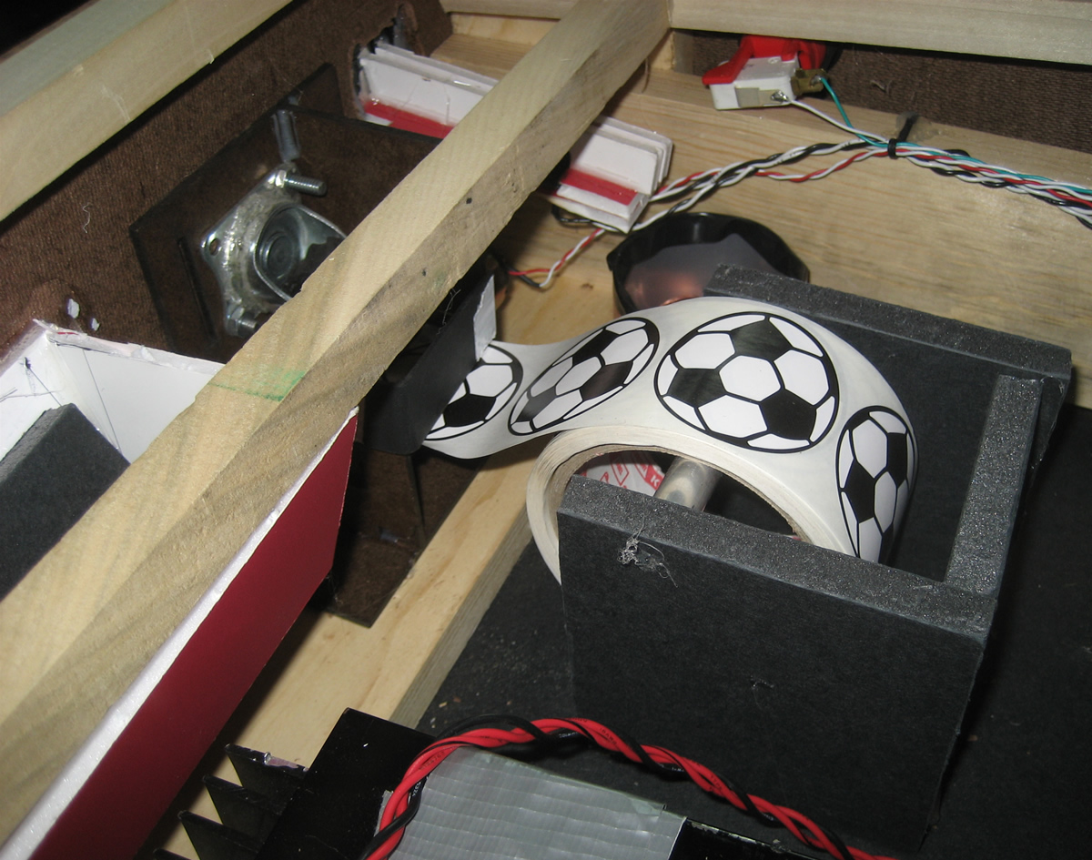
For our swag, we chose to dispense soccer themed stickers, which slide between two wheels, one motorized and the other passive. The motor was controlled through a unidirectional H-bridge and for a time corresponding to the goal differential (1 goal ≈ 1 sticker). We used Lego truck tires on the wheels to grip the tickets. However if we were to do it again, it would be better to use a wider wheel with a less textured surface, which would be less susceptible to binding or crinkling the stickers.