ME218B

Winter 2008
drive to the Spot - Deliver the Ramps - Sort the Balls
Overview:
We landed on the spot...Phase II is begun. The first step was to start requesting balls from the dispenser -- no point in wasting any time. This meant initializing an interrupt timer for the servo pusher mounted on the front of the bot. The servo would depress the dispenser button for a full second, then release it for one tenth of a second and repeat. We kept this simple cycle going for the rest of the game, even during the dispenser’s ten second pauses, as a matter of simplicity. Check out our servo details below...
With the ball requester up and running, it was time to deliver our ramps. Since Goals 1 and 3 on the board were symmetrically opposite one another, we built our robot so that the two ramps extended symmetrically to these two spots. This way, board side didn’t matter, and we didn’t have to aim ramps as long as we lined up in front of the dispenser well. Check out our ramp geometry below...
We used geared motors with foam wheels to rotate and extend our spools of measuring tape, a simple, homebuilt, yet effective solution. The foam wheels could only dispense the tape, so we built a hand-held, battery operated spool rewinder to retract the ramps between runs. Check out our ramp extension details below...
With the angles and heights pre-calibrated, all we had to do was stop the ramps at the right time. This was done simply and effectively with a tape sensor a piece. The sensors were placed below the extending ramp and a piece of back tape on the underside of the ramp at the point of full extension. When the sensors detected this tape, the ramp would be stopped. When both ramps had been stopped, deployment was finished.
On to Phase III...Sort the Balls
Ball Dispenser Servo:
This was a simple but highly effective component of our design. We had to have some way of depressing the dispenser button for at least a second at a time. Many groups were simply ramming into the button and then backing up, which worked well. However, with our use of ramps, it was important for us to remain stationary so that balls would not be shaken off during deployment. We were being especially conservative about this danger because we thought that no balls could be left on the board for the clock to be stopped -- this was sadly a misreading of directions.
We chose to use a standard servo, mounted on the front of the robot, to push the dispenser button. After getting the required angles and duty cycles calibrated for button pushing and release, this was a simple piece of code with an interrupt timer and a PWM channel.
(Pictures of this feature will be coming soon)
Ramp Geometry:
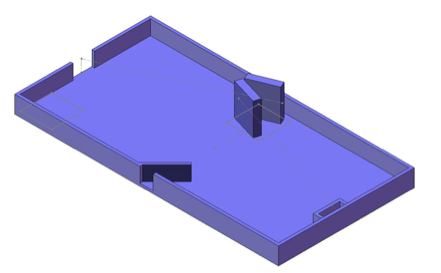
Essential to our strategy are the tape dispensers which quickly and accurately deploy tape measure tape from the robot’s final position beneath the ball dispenser to the two opposite goals, 1 and 3. In order to avoid the mechanical complexity of aimed taped dispensers, we determined that with sufficiently reliable initial robot placement, symmetrical, fixed tape dispensers would be able to accurately deliver balls to their respective goals regardless of which side the robot was playing. However, this approach required a good definition of the design space and considerable optimization work using CAD software.
We started with an accurate model of the playing field then added the robot’s volume envelope in its assumed final position. From our initial tinkering, we knew the tape dispensers would be at most 2.5” wide, and the longer that we could make them, the better for the accuracy of the tape. We also knew the dimensions of the gear motors that would have to be mounted to the rear-sides of these dispensers for their operation. With all of these dimensions, we were able to develop an optimized CAD model for a robot of our volumetric envelope equipped with two of these maximum-length dispensers arranged to dispense balls symmetrically to opposite goals from underneath the ball dispenser. The geometric sketches and model are shown below:
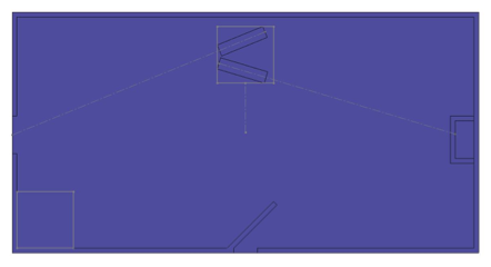
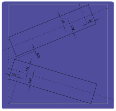
We then needed to know the maximum possible height for the tape dispensers in order to achieve the maximum rolling angle for the tape ramps which would in turn facilitate reliable ball delivery. Because we were designing for symmetry, both ramps needed to be able to clear the walls surrounding goal 3. However, the tape dispensers needed to be below the hopper/sorting mechanism that would be receiving and distributing the balls from the ball dispenser. Based on our initial experiments, we determined that the ball sorter would require a height of at least 3.5”. When combined with our maximum envelope and optimal tape dispenser dimensions, this provided tape ramp angles of 1.5 degrees which we decided would be sufficient for ball delivery.
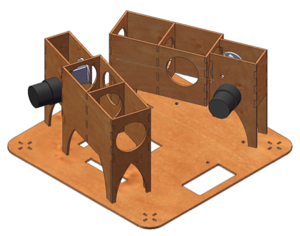
With knowledge of the optimum length, height, and arrangement of the tape dispensers, we were able to create a concrete design based on 1/8” laser cut masonite. The result was the dispenser design shown below:

Ramp Extenstion:
1.Structure
Each Tape Dispenser is constructed of similar 1/8” masonite parts and is identical to the other in function. Each has three stages of tape direction: The first stage (closest to the tape winding) has a thin slot through which the tape passes, the second stage has a notch on which the tape rests, and the third stage has no intended contact with the tape but was intended as a final guide for the ball as it rolls out of the dispenser. The first two stages insure that the tape is accurately dispensed while the third insures that balls consistently remain on the tape as they roll towards the goals. By adding small shims on the second stage, the precise termination level of the tape is controlled. The rear section of the structure holds the tape winding and contact wheel while a large hole between the first and second stages allows balls to roll freely onto the tape. Both structures were designed with a minimum of support to allow a flexible space underneath for the mounting of electronics, and small differences in the two were necessary to accommodate features in the dispenser plate such as holes for the wheels. (shown below)
2.Tape Winding
Our robot’s means of ball delivery depended on two lengths of tape measure tape, each approximately 3½’ long. In order to fit within the robot’s maximum envelope, we needed some means of compacting and storing this tape before deployment. We had already taken apart the purchased tape measures in order to make them our own and gain better control over their behavior. The logical solution for storage was to wind the required length of tape around a mandrel as it had been inside the tape measure. This mandrel is constructed from 1/8” masonite and mounted on a simple shaft consisting of a wooden dowel.
3.Contact Wheel
In order to deploy the tape ramps, our robot relies on a foam wheel that maintains compression contact with the tape at all times. This wheel is coupled to the shaft of a Hsieng L332 DC gearmotor that provides the motive force for the tape extension. Because we did not feel that retracting the tape was a critical part of our game strategy, it requires manual reverse actuation of the tape winding shaft. To this end, we built a battery-powered manual rewinding device that proved quite useful throughout testing. (Pictured below)

To drive the motors, we used a uni-directional quarter bridge -- simply an N-Channel power MOSFET -- since our contact wheel was unable to retract the ramp. You can see our circuit diagram for this on the “Electronics” page at the top.
Stopping the Ramps:
This part was deceptively simple. We simply positioned a tape sensor under each ramp. When the sensor detected a piece of black tape we put on the underside of the ramp, the C32 would turn off the gate signal to the motor.

Phase II: double bladed glory
Component Breakdown:
*Ball Dispenser Servo
*Ramp Geometry
*Ramp Extension
*Stopping the Ramps