Winter 2008

ME218B
drive to the Spot - Deliver the Ramps - Sort the Balls

Overview:
The first phase of our complex stratagem was to drive our robot to the ball dispenser and park it right out front, with the dispenser button within pushing range of our servo arm.
To do this, we needed to drive some wheels on a base first and foremost. Check out the wheel driver details below....
With this detail taken care of, we first needed to rotate in place until we detected the 50% duty cycle dispenser beacon. Check out beacon detection details below...
Next we drove forward until we encountered the black tape. We mounted this tape line and followed it all the way to the dispenser tower. Check out the tape sensing details below...
When the final T-stop at the end of the tape was encountered, we drove forward for another half second, in order to push up against the tower and make sure we were squared up. This final alignment was key to making our ramp deployment accurate. After this, Phase I was complete.
On to Phase II...Deliver the Ramps.
Motor and wheel controls:
Our goals in designing the drive train were simplicity and reliability. Because our strategy only required that our robot successfully reach the ball dispenser in a timely manner once at the beginning of the game, we did not feel the need to spend considerable time and effort creating a creative or high-performance drive train. Instead, we created a compact mobile platform that would occupy a minimum of our available volume first then focused our design efforts on the other two elements of the robot. The features of the original mobile platform design are shown and described below:
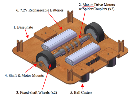
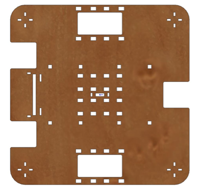
1.Base Plate
The base plate is responsible for providing the structure of the mobile platform and a means of mounting its functioning components. It is laser cut from 1/8” masonite. We selected a square shape to maximize the available space for the remainder of the design but significantly rounded the edges to reduce the danger of catching on a wall at the start of the game. The large holes provide clearance for the wheels and the ball casters while the smaller holes are mostly used to hold the interlocking teeth of the various mounting parts. The long slot on the left provides a viewing port for the front tape sensors as does the small slot in the very center of the plate.
2.Maxon Drive Motors w/Spider Couplers
As required, the robot is driven by a pair of Maxon A-max 22mm DC gearmotors. These are coupled to our machined brass drive shafts via dampened spider couplers designed to reduce lateral, transverse, and rotational shock loading on the gearbox and motor.
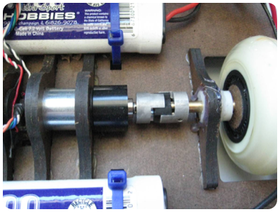
3.Fixed Shaft Wheels
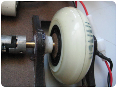
The robot rides on a pair of rollerblade wheels whose bearings have been removed. In order to cheaply and easily rigidly affix the wheels to the shafts, we filed flat surfaces on the shaft and filled the resulting internal space in the wheels with hot glue. In order to achieve and maintain proper shaft alignment during curing of the glue, we used laser cut masonite holders that were screwed to the wheels then later removed. By tightening down these holders while the glue fill was still molten, we were able to apply significant pressure that insured a thorough fill. Our original design called for these holders to be left on, but we determined that the cured adhesive was bearing the majority of the load and clearance between the wheels and the base plate could be improved and the risk of jamming eliminated without them. The only drawback to permanently assembling the wheels and shafts in this way was some difficulty in making repairs or modifications to the overall drive assembly later on.
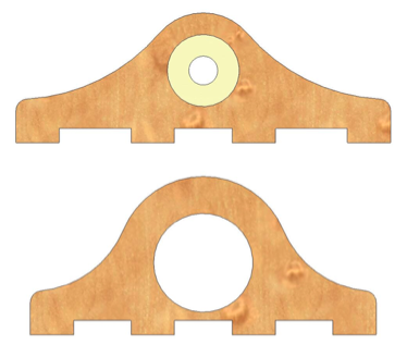
4.Shaft and Motor Mounts
The motors are press fit into 1/8” laser cut masonite mounts (below). Machined ABS journal bearings for the shafts are similarly press fit into 1/8” laser cut masonite mounts and further retained with hot glue (above). Each of the mounts is held to the base plate with interlocking teeth and wood glue.
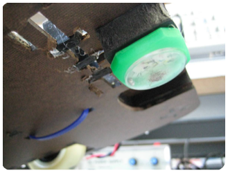
5.Ball Casters

The original design called for three, low-cost steel ball casters to provide omni-directional support to the robot. However, we determined that these casters were too heavy and instead used the slippery plastic watch faces that had worked well in lab 8. These watch faces come from the swag purchased from last quarter’s “The Claw” project and are held onto the bottom of the robot with hot glue and foam core. The height of each face is carefully tuned to maintain full loading on the drive wheels while minimizing rock of the robot.
6.7.2 V Rechargeable Batteries
Both of the two 7.2V rechargeable batteries are mounted to the base plate with zip ties. By fitting the batteries into the mobile platform, more space is freed in the remainder of the robot’s allowed volume and all of the higher-voltage drive elements of the robot are isolated from the control electronics. The connection terminals are routed to the outside of the mobile platform to facilitate charging.
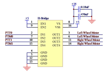
7.Wheel Driver Circuit
We used two TLE-5206 5A H-Bridge DC motor drivers to run our drive wheels.
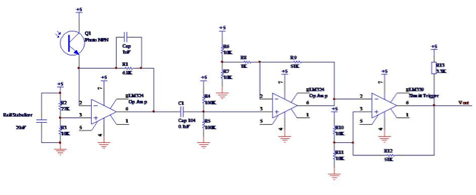
Beacon detection:
This is the circuit for out long range beacon detector:
And here is the far simpler circuit for our flash detector.

Tape sensors for tape following:
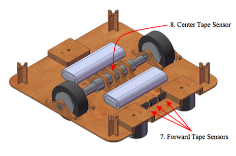
We used a total of 4 tape sensors to facilitate accurate and reliable tape following, three in the front of the bot and one in the center of rotation of the base. We calibrated the height of the sensors experimentally to give the most consistent and distinct A/D input signal change when moving from white to black tape. The front three were used to both to determine the side of the tape and board we were on and to follow a straight line of tape. The rear sensor was used in mounting the tape and in navigating a turn.
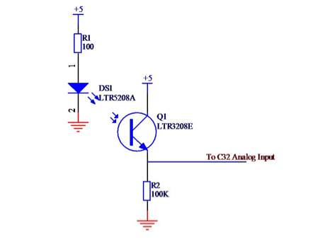
Here is the simple circuit for our tape sensors:
Our general tactic in driving to the dispenser spot went as follows (check the code section to see the actual software state machine):
1. Once the dispenser beacon was detected, drive forward.
-
2. The first front tape sensor (right or left) to be triggered will tell us the side of the tape we are on and which board side we on. (This is because we are always approaching from an angle, starting in the corner and driving toward the centered dispenser. After testing, we found that only a slight angle was needed to differentiate sides reliably.)
-
3. When the rear sensor detected the black tape, our bot was centered over the tape. We then stopped driving forward and rotated in place onto the line based on the side of tape we were on -- if we started on the left side of the tape, we would rotate left to mount it. This stationary rotation was a planned advantage of having our wheel centered on our base.
-
4. Once the front middle tape sensor detected the tape again, we had mounted the tape, aligned along our wheel axis. We then started driving forward.
-
5. Following the tape meant driving forward and making small corrections if we drifted off. The middle sensors was always on the tape, but if one of the side sensors drifted on, we would arc back in the opposite direction.
-
6. When all three front sensors went off the tape, we had found the corner turn. From there, we drove forward.
-
7. When the rear sensor also left the tape line, the bot was closely centered on the corner. From there, we rotated in place toward the beacon, depending on the board side we had already determined we were on.
-
8. When the middle front sensor hit again, we had found the second part of the tape line. We followed this in the same way as the first line.
-
9. Once all front tape sensors detected the tape, we had found the T-stop in front of the dispenser.
-
10. From the stop, we drove forward for another half second to push up against the dispenser tower and make sure we were squared and positioned correctly.
Mission accomplished. We were at the spot.
On to Phase II...Deliver the Ramps.
Phase I: Hipity-hop, Get this bot to the spot


Component Breakdown:
*Wheel driving
*Beacon Detection
*Tape sensing