Winter 2008

ME218B
drive to the Spot - Deliver the Ramps - Sort the Balls
Overview:
Now for the good part...and also the part that caused all the mistakes. We were positioned correctly, our ramps were extended to the goals, and our ball hopper was slowly filling. Next we just needed to get the balls down the right ramps.
We used a rotating carousel, similar to a pistol revolver, to process our balls. The carousel was turned by a motor and a simple, closed loop control system that kept the rotation slow but prevented the carousel from getting stuck by friction.
As the carousel turned, incoming balls would fall into open slots, plastic tubes with an open section facing outward. We then had to check each ball individually to see what color it was in order to direct it to the correct ramp. To do this, we cut a notch in the carousel in front of each ball slot. An opto-interrupter detected each notch and told us when to take a ball color reading with a tape sensor. Check out this whole ball hopper system below....
Once the color was detected, the ball would rotate on and fall down a hole in the carousel to the ramps. But, before this fall, we would process the ball color and switch our gate servo to direct the ball to the correct ramp. We sent all the black balls to Goal 3, along with the first 6 yellow balls. This decision was based off a poor reading (or writing) of the game rules. Our strategy depended on ending the game quickly, by processing the balls as fast as possible, and thus preventing other teams from dumping their balls in the goals. We thought that to stop the clock we needed not only to dispense all the balls but to have no balls left on the board. Therefore, we were playing it very conservatively in how many balls to channel into Goal 3, ensuring that non fell out. It turns out that this was a misreading of the rules; instead, to stop the clock there could be no more balls left “ON BOARD” (the ROBOT), no the playing board. Learning this, the best tactic would likely be to send all balls to Goal 3, without ball sorting complexities.
Finally, we needed to get the balls to roll down the ramp. Our angles were very shallow, so the balls would often stop unaided. To fix this, we added three sweet fans, one to blow the balls to the ramps and two more to blow them down the ramps. This worked great. Check out this whole ball sorting system below...
The major problem with this whole system was that balls would often get stuck in our rotating carousel. When an extra ball was in the carousel, it would sit on top of another in one of the slots. When this slot rotated under the guarded section, where the drop hole was located, the top ball would get pushed off. However, it would sometimes get stuck against the guard when falling into the next hole. To prevent this, we added a kicking motor to the carousel side wall that would block extra balls from making into this danger zone. The idea was to have every ball safely within a hole before going beneath the guard, to prevent jamming. This worked well, but was still not infallible. Check out our anti-jam crazy-legs kicker below...
Ball Hopper and Sorting:
Based on our knowledge that goal 3 could not reliably hold all 20 balls and our belief that balls left on the playing field counted against us, we determined that it was important to send only a certain number of balls to the higher scoring goal 3 and the rest to goal 1. In addition, we realized that it was important to get the higher scoring black balls into goal 3 to maximize our points scored. To address these needs we devised a means of sorting and distributing the balls from the dispenser to goals 1 and 3. This solution consisted of two main parts, the rotary ball hopper and the ball sorter.
Ball Hopper
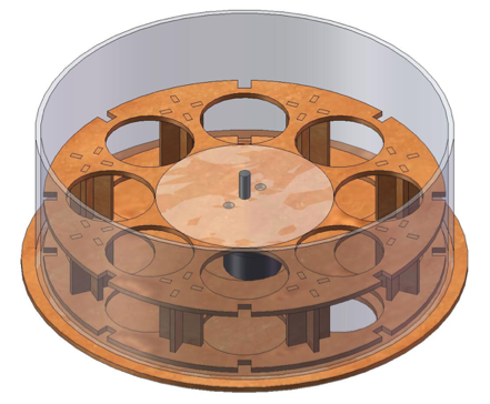
The purpose of the rotary ball hopper is to absorb different rates of input of balls while identifying their nature (black or yellow) then providing a constant, manageable rate of feed to the ball sorter. Because ball sorting is very important to our robot’s strategy, the ball sorter needed to be reliable. In order to achieve that reliability with a simple design, as discussed later, the sorter needed ample warning time to switch its distribution direction based on which color ball was coming to it next. At the same time, our strategy calls for immediate request of balls upon the robot’s arrival at the ball dispenser in order to speed our completion of the game. Because the tape has not yet had the time to deploy when the robot first requests balls, our robot would inevitably develop a backlog of balls in the beginning of the game that would need to be digested. As designed, the ball hopper succeeded at solving these problems but had jamming problems. Some modifications brought it close to the desired level of reliability, and the components of the final hopper are shown and described below:
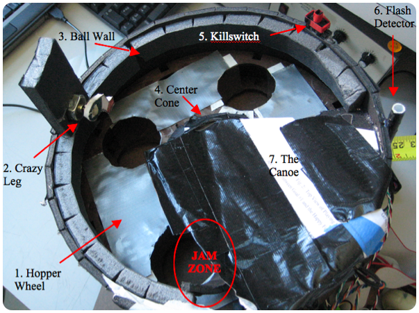
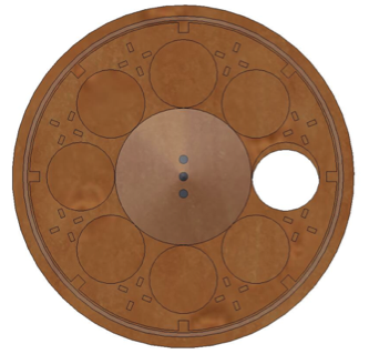
1.Hopper Wheel
Originally designed to hold 8 balls at a time in segregated holes, the hopper wheel was eventually modified to hold only 4 balls at a time in order to slow feed rate without having to further reduce rotation speed into the friction sticking range. The wheel is continuously driven by a Hsiang NEMG DC gearmotor with speed control based on the measured intervals from the notches reaching the opto-interruptor (8). (Insert description about construction from Will’s)
2.Crazy Leg
This continuously spinning leg helps to keep balls away from the jam zone by knocking them back and generally agitating them. Occasional balls can still jam the crazy leg or bypass it to jam the hopper wheel in the jam zone.
3.Ball Wall
This extra-thick section of wall helps keep balls located above the holes in the hopper wheel and away from the jam zone. In the jam zone, the wall curves inward to further reduce the possibility of jam.
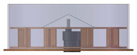
4.Center Cone
Working with the ball wall, the center cone helps to keep balls in line with the holes in the hopper wheel where they can fall in. The cone needed to be cut short in order to accommodate the canoe (7) without causing jams between the ball dispenser and the robot.
5.Killswitch
As required in the rules, this easily reached switch cuts all power to the robot, stopping it if it gets out of control.
6.Flash Detector
After considerable trial-and-error, we determined that encapsulating our phototransistor flash detector in a medium-height tube is the best way to consistently see the flash while filtering out false flashes.
7.The Canoe
Deriving its name from its original canoe-shape, this modification is a simple multi-sheet stack of paper designed to direct balls from the ball dispenser away from the jam zone to give them the maximum opportunity to drop into the ball hopper. After many design iterations, we settled on the above configuration that is given rigidity in certain areas with tape. The canoe also served in part to physically keep balls away from the jam zone that made it past the crazy leg.
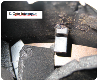
8.Opto-interruptor
The opto-interruptor works in conjunction with periodic notches cut in the hopper wheel to serve two functions. First, its signal provides a sort of rough encoder feedback for the rotation of the wheel which allows the variable duty cycle control of the motor to “power through” sticking points due to ball jams or friction. Second, the opto-interruptor is positioned such that it is triggered only when a ball is in sensing range of the ball color sensor (9). This guarantees accurate ball identification regardless of rotation speed and no need for stopping.
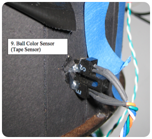
9.Ball Color Sensor
The ball color sensor is a tape sensor horizontally mounted in the wall of the ball hopper facing the ball that is about to drop down to the ball sorter. When triggered by the opto-interruptor (8), this sensor provides reliable black-or-yellow information to the ball sorter well in advance of ball delivery helping to reduce jams.
Ball Sorting:
The ball sorter performs the important function of determining which ramp each ball is sent down insuring that black balls are always sent to goal 3 and goal 3 is not overfilled. Like the ball hopper, CAD models do not accurately capture the ball sorter, and the components of the sorter are shown in a picture and described below:
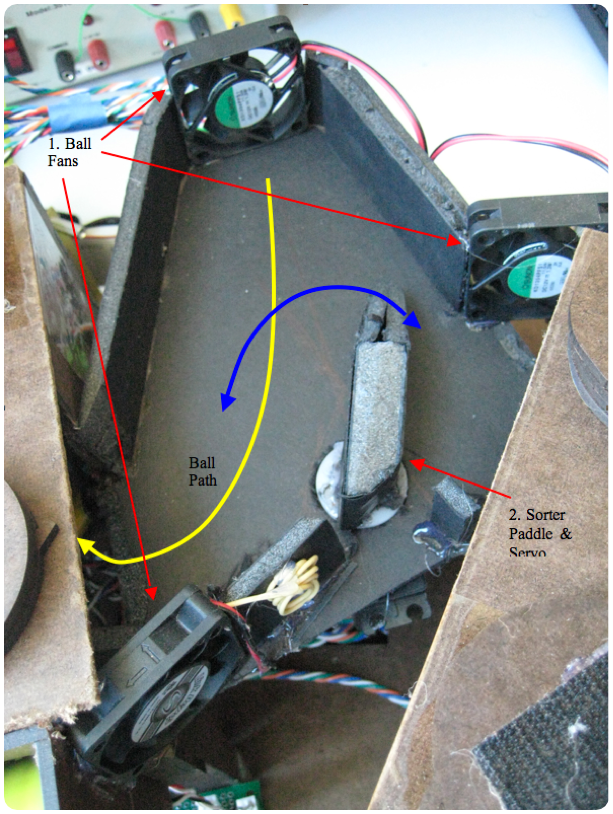
1.Ball Fans
Although the ball sorter and tape ramps were originally intended to function with gravity alone, we decided to add three fans to help the balls along through our system. The uppermost fan pushes balls just dropped from the ball hopper through the sorter while the other two push the balls into and down the tape ramps. The lowermost fan is particularly critical because of the sharp turn the ball needs to make from the sorter to the tape ramp.
2.Sorter Paddle & Servo
The sorter paddle is a simple foam core wedge driven by a servomotor mounted on the underside of the sorter ramp. Its range of motion is tuned to direct balls into either tape dispenser at its extremes. Because of its simple design, the ball hopper’s controlled rate of feed and advanced ball color warning were essential to its reliable functionality.

Phase III: Spin the wheel of fortune


Component Breakdown:
*Carousel Driver
*Ball Detection
*Servo Ramp Gate
*Fans Controller
*Crazy Legs