
Construction
In addition to the Helm and Ship construction specifics below, you can view the design team's Weblog, titled "Decrypt This" for more insight into their progress during the development process.
Helm
The Emergency Satchel is designed to appear to the layman as a standard black leather briefcase. It is only the secure wrist connection that belies another purpose. Within the lid is a set of operational instructions, prepared for your review aboard Air Force One and included in your daily briefing.
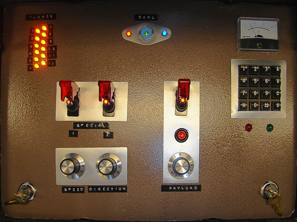
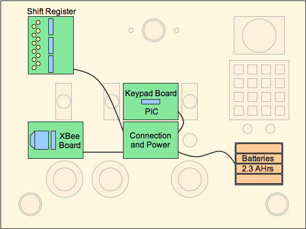
On opening the case, rare-earth magnets located along the outer edge of the lid will toggle an enable switch, located just under the main control panel. This panel is constructed of foam-core supported from below, to minimize overall weight. Robust, tactile controls are secured into the panel and connected to a single PIC microprocessor, supported by XBee and shift-register circuits. These are mounted on control boards below the panel.
In keeping with design requirements, the helm provides four sensory interactions:
- Mechanical (use of toggle switches, pushbuttons and potentiometers)
- Magnetic (a Reed switch enables the control panel on opening the case)
- Timing (the arming keys must be turned within 0.5 sec of each other)
- Sequence (the keypad is enabled and cleared only by the correct code)
Below is the control panel layout shown from directly above, alongside a schematic of the circuit boards just beneath it.
 |
 |
Ship
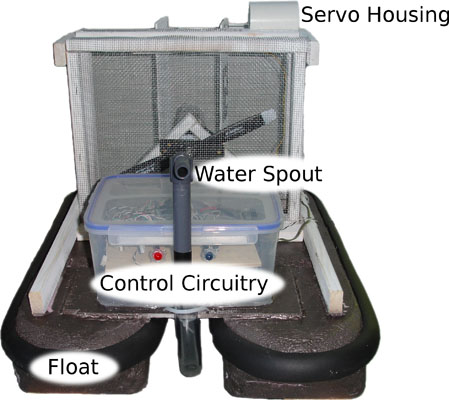
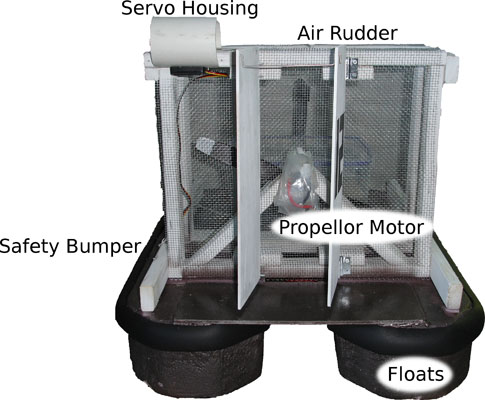
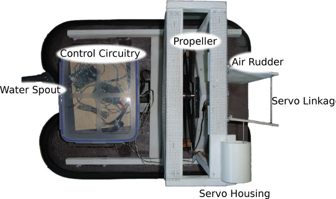
The default vessel for operational control is a modified airboat design. The main motor and propeller are housed within a safety enclosure (cage) at the stern. Connected directly aft is a dual-rudder system, controlled by a servo and driven by a linkage of 1/16" stainless steel wire. Connected directly fore is the payload release motor (bilge) and connective hosing that directs flow outward from the bow. Toward the stem is a waterproof housing for the electronics, which include two PIC microprocessors for communications, operation and PWM control of the propeller and rudder motors. These are supported above the deck by a raised platform, in case water should infiltrate the compartment. The main transistor within is tolerant of 98 Amps of current. This entire structure is a self-supporting frame, which is mounted atop two flat-bottom pontoons, contoured from light-weight foam for high-speed operation.
 |
 |
 |
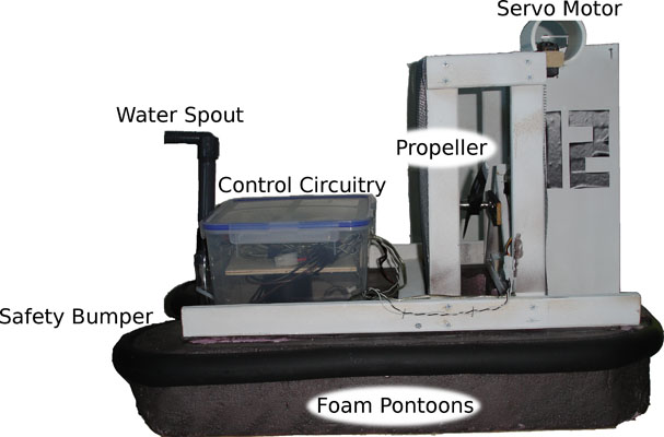 |
To keep the bow from pearling: (a) the center-of-mass of the self-supporting frame was positioned toward the stern, and (b) the propeller was aimed slightly upward. The motor mount was designed and the hull was shaped to keep the propeller as low to the waterline as possible but above it by 2-3 inches. During one test, the propeller came loose and excised a portion of the hull, but the safety cage enclosed it. Once integrated into the design, the safety cage served as a mount for the rudders and servo. The initial linkage was constructed of 3/8" wood dowels connected by eye-hooks, but it was over-constrained and abandoned for the taught wire-assembly shown below.