|
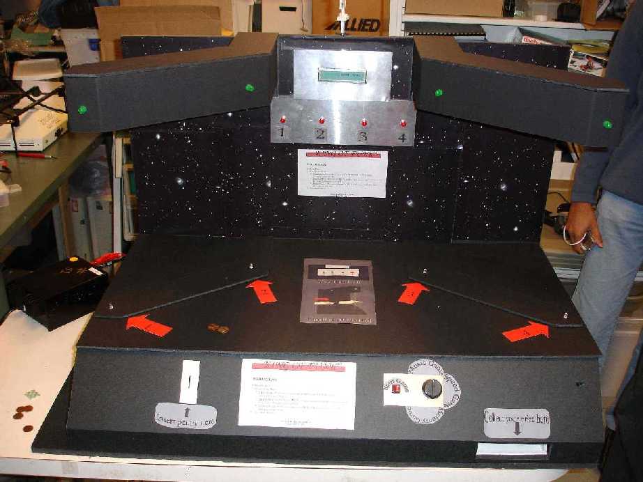
This section describes the design elements of the game.
Components/Elements: Coin sensor, Difficulty level (POT), Game Start (button), Electromechanical reaction (twirling doll), LED's, Hand movement detection, Display, Music (How we hacked the music!), Dispensing Prize, Structural schematics
The project is a memory game in which the user has to remember a pattern of 4 LEDs going on and off. He/she should then repeat the same pattern by moving his hand in the same pattern, each movement corresponding to breaking a particular IR beam. The score is calculated on the basis of how much of the pattern the user got right.
Pin outs in the following schematics correspond to pins on the C32 as following:
Pins 1, 28: No Connect
Pins 2, 3: E0, E1
Pins 4 11: T7 T0
Pins 12, 13: M0, M1
Pins 14, 15: Ground
Pins 16 19: M2 M5
Pins 20 27: AD7 AD0
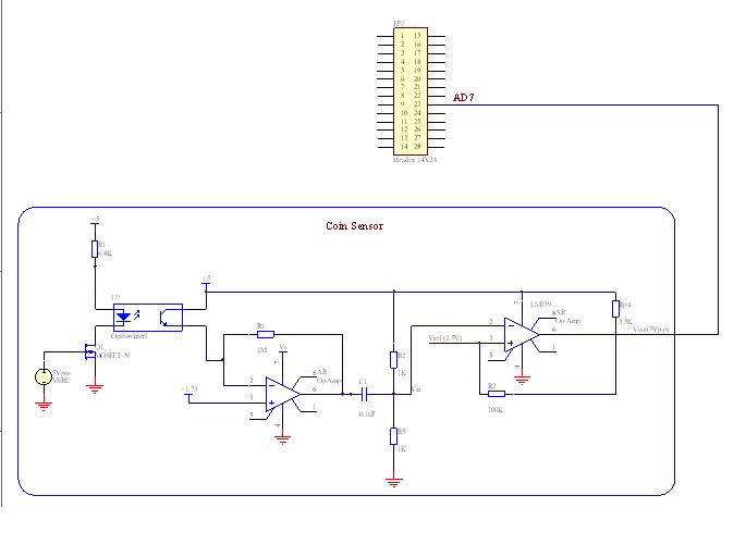
Coin Sensor
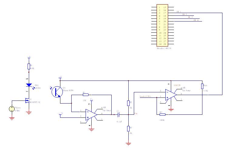
Coin is sensed using a coin sensor (opto-interruptor). The coin sensing action is converted to a digital input for the C32 using a trans-resistive circuit and a comparator in an inverting configuration. When the coin is detected the output of the circuit goes high. This feeds as an input to Port AD7 of the C32. The state of this Port AD7 decides if the user can play the game or not.
Return to Top
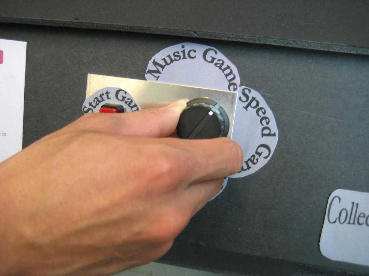
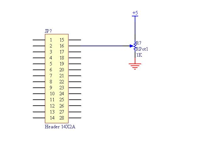
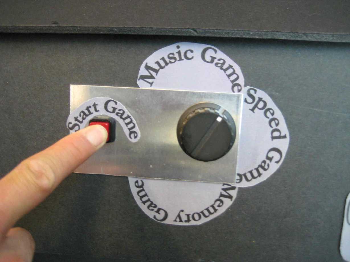
Difficulty Level (POT)
Using a knob on the MPAG, the user can select the difficulty level for the game. A potentiometer with a control knob served the purpose of a dial that the user could use to select the mode of the game. This will be achieved using a potentiometer, the output voltage going as an input to port AD0.
Return to Top
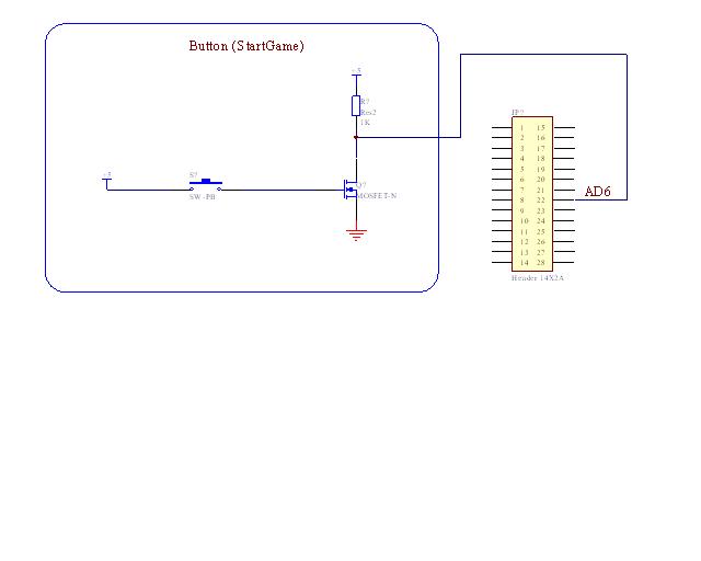
Game Start
This switch triggers the game, outputs instructions to the LCD screen and starts the first LED pattern. The switch is a momentary switch and the input goes to Port AD6 of the C32. A simple momentary switch was used for the user to start the game.
Return to Top
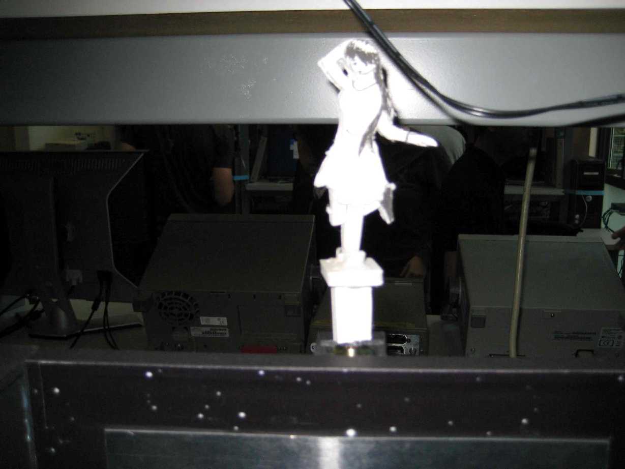
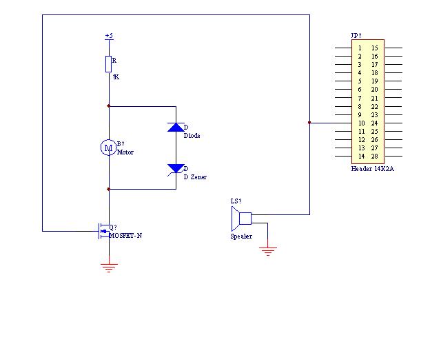
Electromechanical Reaction (twirling doll)
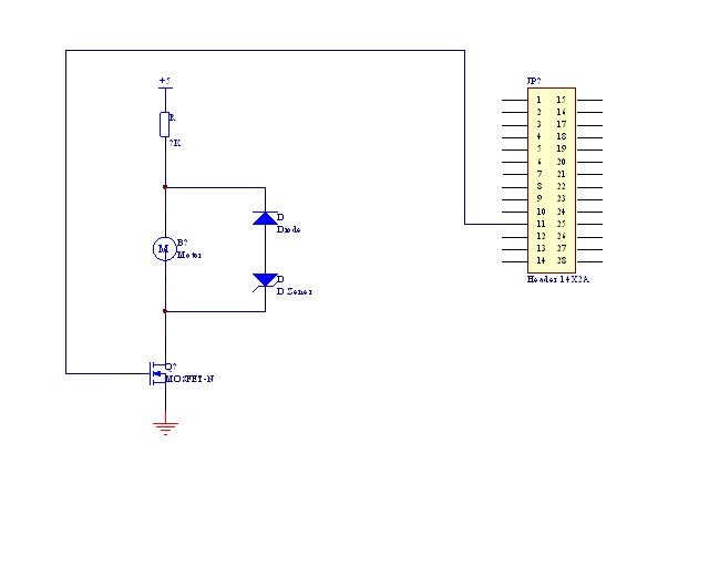
A Doll twirls if the user is on a winning streak i.e; if the user has got a particular number of consecutive movements of the pattern right. This is our electro-mechanical reaction. This is controlled by Port T1 of our C32. We require the doll to twirl in only one direction hence the circuit is simple and does not require PWM or H-bridges. The spinning doll was a reaction from the game for particular inputs from the player. The doll was a simple foam core shape cut out that was mounted on a motor whose speed of revolution was controlled by PWM.
Return to Top
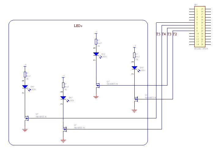
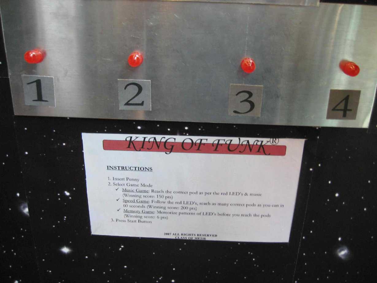
LED's
The core interaction of the MPAG is the red LEDs lighting in a particular pattern and the user being able to copy/retain this pattern. The LEDs switch on and off according to a pattern corresponding to the game the user has selected. In the memory game for example the LEDs would light up according to the pattern the user was to memorize. The music and speed game would follow a random selection of which LED to light up , the time being controlled by either the beat of the music or the level of the speed game respectively. The pattern of the LEDs is controlled by the ports T2 T5 of the C32.
Return to Top
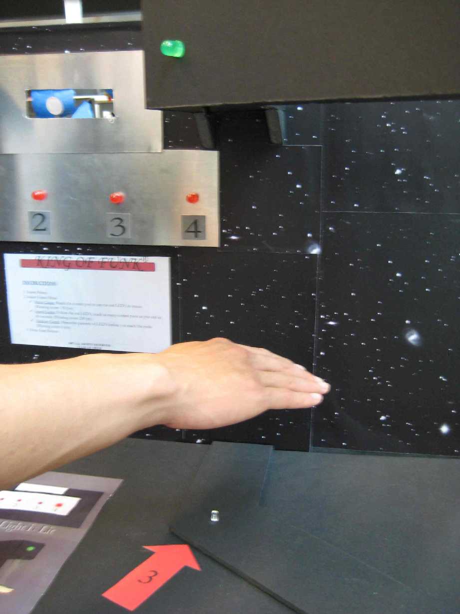
Hand Movement detection
The user recreates a pattern by moving his hands to particular slots (spaces). Each space corresponding to one of the red LEDs that had gone on. This motion detection occurs with an opto-interrupter circuit that we will make. The key would be to find the maximum distance we can keep between the IR LED transmitter and receiver and ensuring one IR LED does not interfere with another. The distance we are aiming for is about a foot, this space would be sufficient for easy movement of the hands for the user. The inputs from these circuits to the C32 would be through ports AD1 to AD4. The Pods were IR beam columns created by a IR emitter and a Phototransistor. Breaking a pod would imply putting your hand in between the IR emitter and the Phototransistor. The Green Jumbo LEDs would go on when the pods were broken. This would give the user an indication of having broken the Pod. There was also an auditory feedback via a sound recorder setup that would indicate having broken the pod.
Return to Top
Display
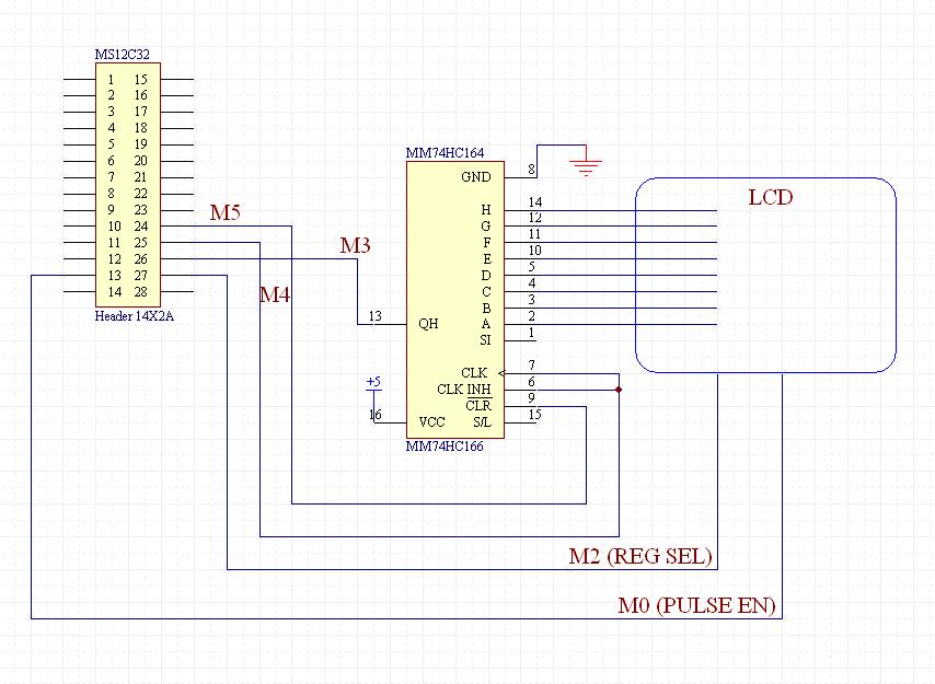
The LCD would serve as the medium of instructions for the user. All instructions like Press Button to start game , instructions of how to play the game and the final score shall be displayed on the LCD. For connecting the LCD to the C32 a shift register would be used and the inputs to the shift register would come from ports M3 (clock), M4 (input) and M5 (cycle). The pulse enable and register select pins would correspond to Ports M0 and M2.
Return to Top
Music
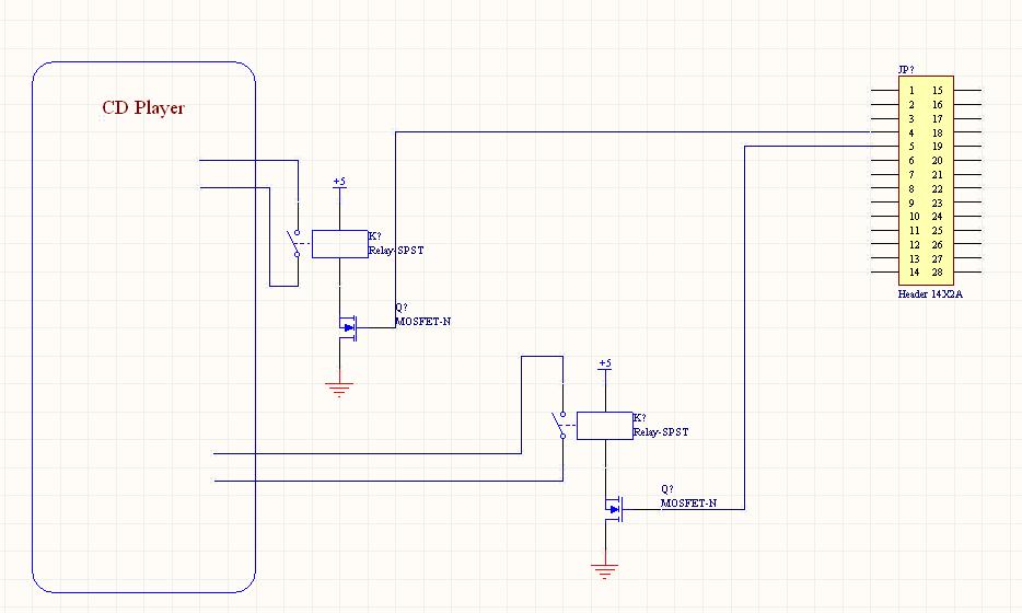
The sound circuit integrates a CD player, speakers and relays. The relays control the START and STOP buttons of the CD player. The relays are controlled via the C32 ports switching the CD player ON and OFF. The output from the headphones hooked up to the CD player is fed into a A/D port of the C32. The CD is not just the usual audio CD player. The music track is fed into MATLAB and the beat of the music is extracted using MATLAB commands. The output to the headphones which is the input to the C32 is a frequency input. Depending on particular thresholds and sampling time a beat is captured by the C32. This becomes the control logic for the LED circuitry.
Return to Top
How we hacked the music!
How to edit a .wav file using Matlab
[y,fs,nbits]=wavread('filename');
Reads the wav file. y contains the music. fs is the frequency, and nbits is the number of bits used to encode the file. fs and nbits will not be changed, but every fs points in y corresponds to 1 second in time.
y(:,2) = 0;
Sets the right channel to zero. You could easily do the same operation to left channel instead depending on your needs.
for i = start:stop
if(mod(i,6) == 0) y(i,2) = 1;
elseif(mod(i,5) == 0) y(i,2) = 0.5;
elseif(mod(i,3) == 0) y(i,2) = -1;
else y(i,2) = 0;
end
end
Puts a pulse into the right channel. Pulse length is (stop start)/fs seconds. Pulse occurs start/fs seconds into the music. Using only Matlab and trial and error, you can place a pulse on certain beats in the music.
wavwrite(y,fs,nbits,'filename');
Writes a new wav file using the edited signal y. Now you can burn this wav file onto a CD which can be played by a CD player. Make sure to burn it as an audio CD.
How to cheaply read an edited track into the microcontroller
You need a CD player, a speaker that plays only right or left channel, which has an audio port to attach the other opposite (right or left channel) speaker, and a pair of cheap headphones you can destroy.
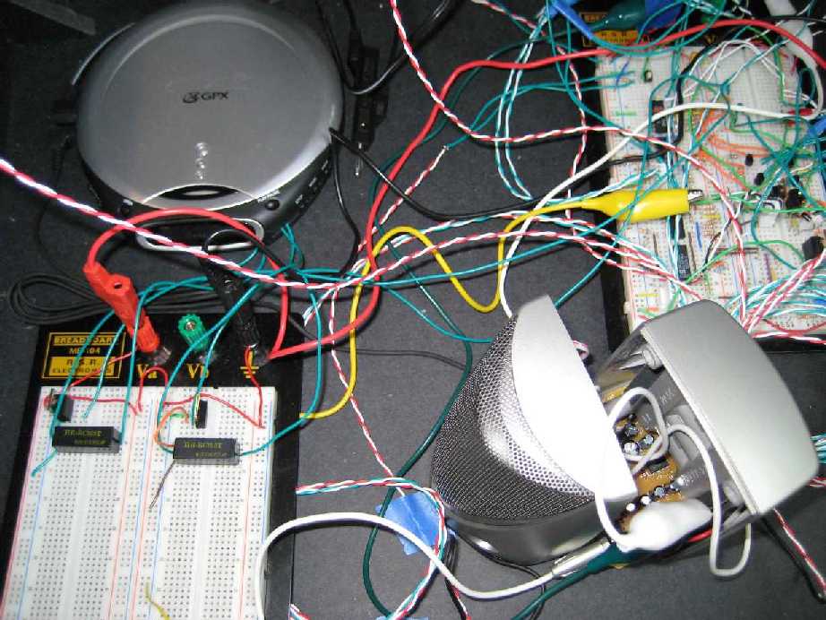
1. Hacking your CD player
a. Open up your CD player by removing all the screws on the back
b. All of the buttons on the outside are connected to buttons attached to the circuit board
c. You can solder wires to the alternate leads of the buttons if they have them. Otherwise, I suppose you could rip off the buttons and solder wires to the connections directly on the circuit board. Shorting these wires has the exact same effect as pushing the button.
d. Run these wires out of the CD player and connect them to relays, so that you can control the shorting of the connection using a microcontroller. The circuit for controlling a relay with a microcontroller is fairly simple. It is available in our schematics.
e. You can do as many buttons as you need, but to play music all you really need is Play and Stop. Skipping tracks would be nice too.
2. Connect your speaker to the CD player. This speaker should only play the channel that you left untouched essentially it should play the music.
3. Connect your headphones to the speaker. The headphones should only play the other channel the one you modified in Matlab. It should essentially sound like a series of high pitched beeps if you use the code above.
4. Cut the headphones wire. Inside the wire should be three different colored wires. One corresponds to ground, the other to right and left channel. Verify experimentally which wire is the channel you want.
5. Now connect that wire to your protoboard/circuit board, and connect the ground wire to your power supplys ground. Using an oscilloscope you can verify that the voltage from the audio wire to ground is zero until an audio pulse, at which point it oscillates.
6. Run the audio wire into a voltage divider in order to ensure that you never read a negative voltage. Run the output of the voltage divider into an A/D port of your microcontroller. Now you can calibrate your values so that you can detect a pulse using a simple if statement. The resulting code is left to the reader as an exercise and is also available in our code listings.
Return to Top
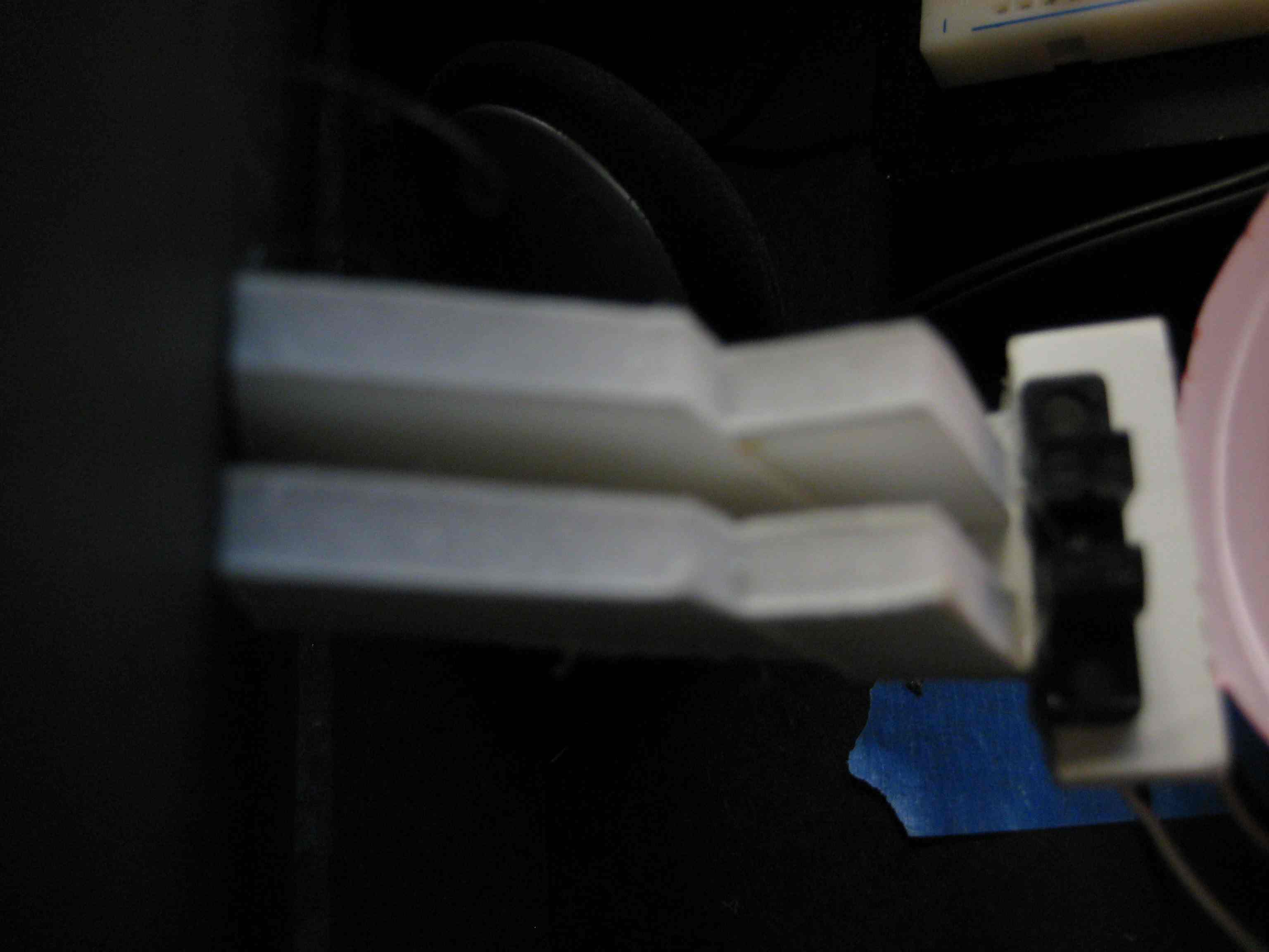
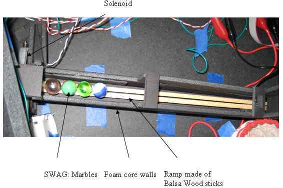
Dispensing the Prize (Solenoid)
Price dispensing on completion of the game would be initiated through Port T0 of the C32. The output would drive a motor to open and close a shutter that would drop a prize (marbles). The prize (SWAG) dispenser is a simple solenoid based ramp arrangement. The ramps are made of Balsa Wood such that the marbles can freely roll down the ramps. The solenoid acts as a simple gate like mechanism that when activated pushes a marble into a collection bin. The setup is simple and does not require the use of more complex electromechanical systems. The SWAG dispenser had to go through many iterations as the slope for optimal dispensing of prizes and the optimal width of prize dispenser had to be determined.
Return to Top
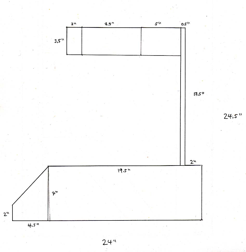
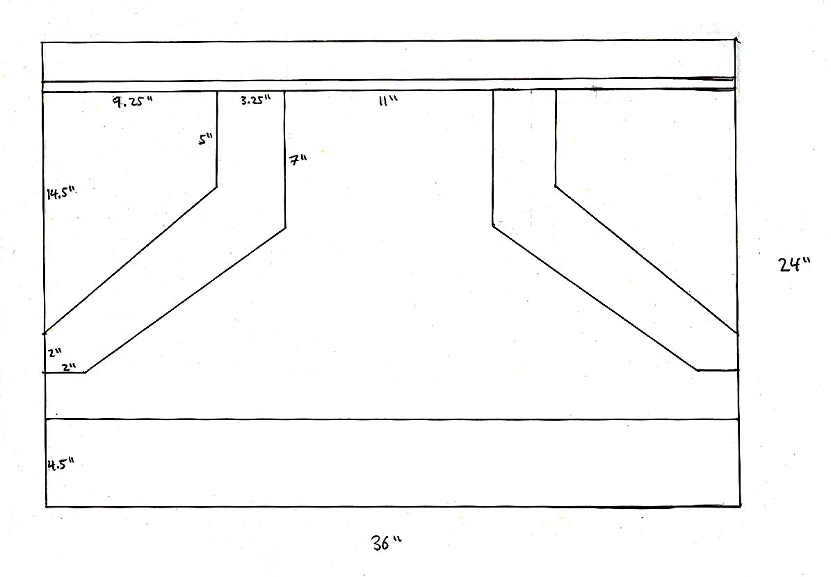
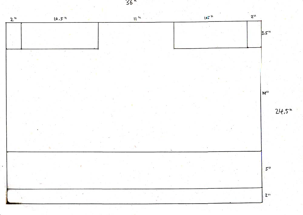
Structural schematics
Return to Top
|