|

Play in the
"Spinning Wheel" game is mediated by two sets of indicator lights:
orange blinking LEDs that correspond to required user actions, and
jumbo LEDs in a 'traffic light' configuration that communicate
timer outputs to the user. In the following paragraphs, game play
is described in relation to both sets of indicator lights.
During idle mode
(between plays), a blinking LED next to the coin slot indicates
that a coin is required for play to begin. At this time, the red
traffic light is lit. After play is initiated, a second blinking
LED next to the level-select knob turns the user's attention
there. Three levels can be selected, which correspond to three
possible speeds on the motor. After several seconds, a third
blinking LED next to the ball-release mechanism suggests to the
user that it is the appropriate time to release the contained
balls. At this time, the amber traffic light is lit for ten
seconds, building suspense for the beginning of play.
When the green
traffic light goes on, the spinning wheel spins for the duration
of the game. A large red LED above the wheel indicates each score,
to a maximum of eight. Balls are stored in a tube next to the
playing surface. With ten seconds remaining, the green traffic
light is replaced by amber, and the end of the game is signaled
both by a buzzer and the red traffic light. A blinking LED near
the SWAG dispenser draws the user's attention there, and a prize
is dispensed. The coin-deposit LED blinks again, waiting for the
next user.

Coin Sensor: This opto-interrupter
is a stock part from the ME218 lab. It contains a built-in IR LED
and NPN phototransistor. In "Spinning Wheel", the opto-interrupter
was fixed to the inside of the coin slot, such that a deposited
penny would break the IR beam.
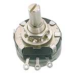
| Level
Selector: A potentiometer was used here as an analog input
to the C32. Based on the resistive value, three settings were
hard-coded to correspond to three motor speeds. The
potentiometer was visually enhanced with a knob on the outside
of the game. |
 |
Wheel Motor: Powered from
the 12V supply, a resistor and reverse biased diode were used in
parallel with the motor to damp down voltage spikes. Please see
the schematics section for more information.
Scoring LEDs: Each LED was
connected to the output of a 74HC164N shift register. The C32 was
used to pulse the clock pin high and then low for each additional
score.
SWAG Servo: The servo motor
was powered with the 5V supply. Its third lead was connected
directly to a C32 PWM pin. Changing the duty cycle of the signal
through that output pin controlled the specific angle of action of
the Servo.
Blinking LEDs: Controlled simply with an NPN transistor, these
LEDs were purchased with the capability to blink at 2.4Hz. Current
was managed with resistors.
Traffic light LEDs: Also controlled directly with an NPN
transistor.

|
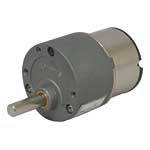
Wheel Motor: A geared DC
Motor (Jameco PN: 253497PS) was used to direct drive the spinning
wheel. It was powered by the 12V supply. The gear ratio was
specifically chosen at 90:1 to make the game fun to play, and
beatable. |
 |
SWAG Dispenser: This
electromechanical system was designed to take a single acrylic
disc from a stack and dispense it to the user, employing a 90°
back and forth motion from the servo.
Ball Release Mechanism:
Designed for user interaction, this simple gate confined the extra
balls inside the holding tube until the user was ready to play. |
