Actuation
Drivetrain
Overview
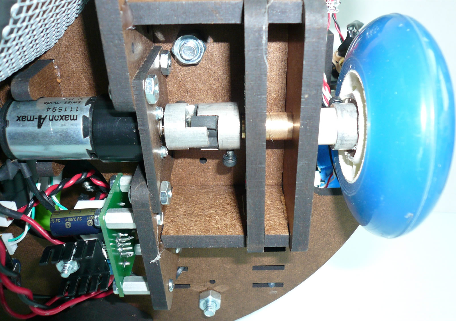
The drivetrain was basic in design, with two rollerblade wheels mounted on the center axis, and two large castors in the front and back for balance.
Hardware
Each wheel was independently controlled by the Maxon motors supplied in class. Spider couplings and custom masonite brackets were used to mount the motors and ensure robust performance of the wheels. The recommended TLE 5206 “kits” were used to control the motors.
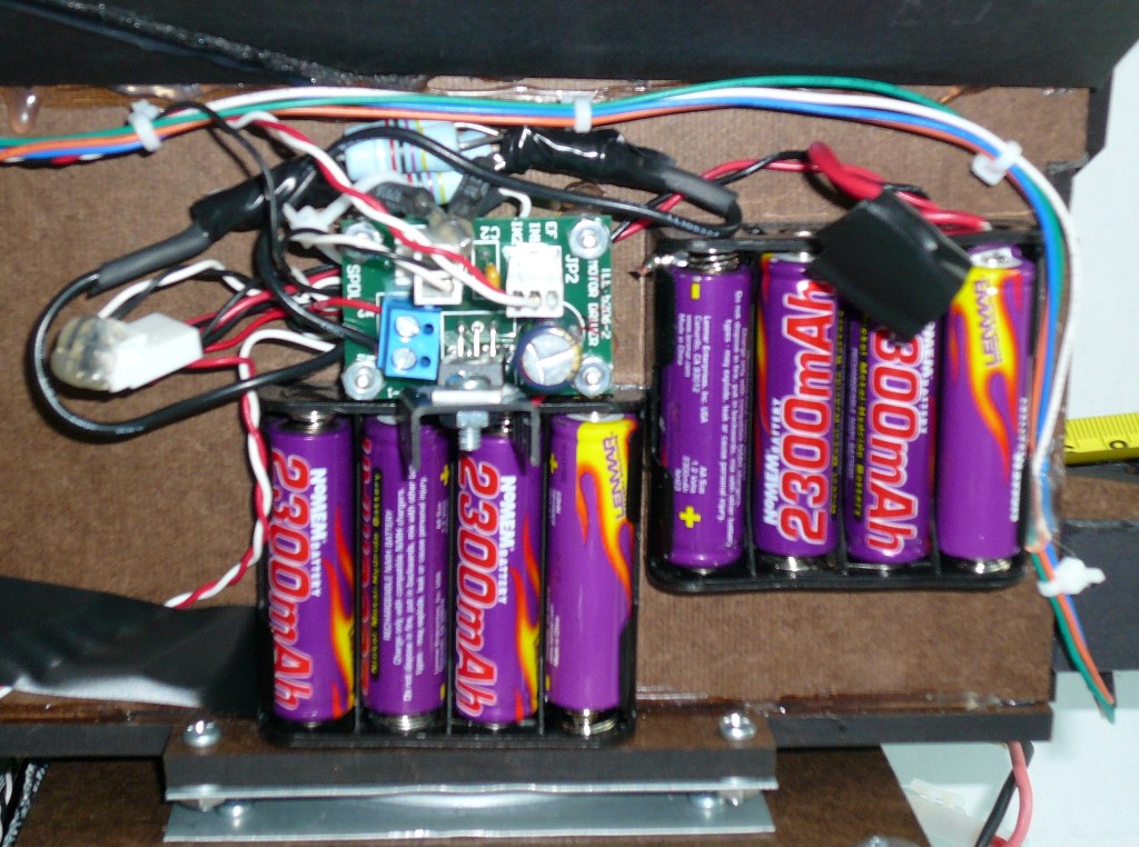
The motors were run off of unregulated voltage from the NiCAD battery packs. In retrospect, we probably should have put a voltage regulator on the motor boards as to avoid diminished performance due to draining batteries. However, we did not learn about high current voltage regulators in class until after our drive train was built and our motor boards assembled. Eh…“ce la vie” we say! We were able to get by by making sure we always had fresh batteries.
The motors were connected in drive brake mode and independently controlled in software. Optimal PWM duty cycles were determined by calibrating each motor individually at the onset.
Circuit
The circuit for the driver is simply the standard TLE 5206 'kit' sold in the TA shop, with no modifications
Turret Drive Motor
Overview
The core strategic part of our robot design was a rotating turret which housed a mechanical tape measure (Thank you Black and Decker!). Upon reaching the ball dispenser, the turret would rotate to align with Goal 3 and actuate the tape measure. A reflective sensor mounted below the mouth of the tape measure would sense when the tape was extended the correct distance. The ‘bot would then begin requesting balls which would then funnel into the turret and gracefully roll into Goal 3.
Hardware
The turret was mounted on a small “Lazy Suzan” made of 2 pieces of stamped sheet metal and captive ball bearings.
The turret was controlled by a Jameco Reliapro DC gear motor scavenged from the Cabinet of Freedom. A spider coupling was used as a shaft hub to ensure a robust connection between the motor shaft and the rotating platform.
The turret needed to rotate in a different direction based on which side of the field it was on. The side was determined in the initial line following stage of the match—whichever front tape sensor hit tape first correlated to which playing field the ‘bot was on. Limit switches at the end of either range of motion were used to sense and hold the orientation of the turret and to aim it at Goal 3. Since the limit switches provided position only relative to the 'bot chassis, the accuracy of our aiming relied exclusively on the precision of the 'bot's orienation to the ball dispenser. The open loop nature of this portion of our game play was the inspiration for our team name.
Circuit
Tape Drive
Overview
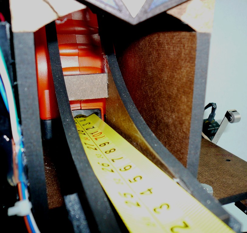
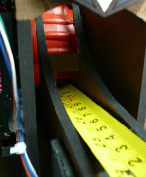
The core strategic component around which our entire robot concept was developed was an off-the-shelf mechanical tape measure (Thank you Black and Decker!) housed in the turret. Upon reaching the ball dispenser, the turret would rotate to align with Goal 3 and actuate a DC motor which drove the tape measure. A tape sensor mounted below and at the mouth of the tape measure differentiated between the reflective yellow of the tape measure and the black strips of electrical tape marked at the minimum and maximum desired travel. These marks permitted us to control the extension of the tape measure very precisely. Once extended, the ‘bot would then begin requesting balls which would then funnel into the turret and gracefully roll into Goal 3.
The solution, though elegant, was not without challenges. In order to compensate for the sag of the extended tape measure, it had to be mounted at a slight, precise angle in order to raise it above the lip of Goal 3, while at the same time maintaining an overall downward grade to the tape measure ramp. The tape measure also tended to draw high currents at start up due to an extremely low armature resistance. Initially a 5206 driver board kit was used to source the necessary current, but even this proved inadequate. The fundamental issue proved to be that the voltage demanded by the 5206 was high enough, and the armature resistance low enough, that there was a very narrow band in which the supply voltage was adequate to power the driver board without drawing excessive current and shutting down the chip. Furthermore, the acceptable supply voltage range did not include either the standard 5V regulated power, nor the 14.4V primary battery pack. Ultimately, the inelegant solution of installing power resistors in series with the motor was used to limit the current it drew, and a secondary set of 8 AA batteries was used to achieve the desired voltage
Hardware
By buying the automatic tape measure as a commercial unit, we were able to simply hack the existing mechanical design of the tape measure and connect directly to its leads in order to control it.
Circuit
Blah