
Sensing Overview
Flash Sensing
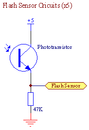
After hearing horror stories from previous 218B alumni about undetected flashes, we went beyond the call of duty and constructed a flash sensing sphere of power. Built from a disfigured Nerf ball and 5 IR phototransistors wired in parallel, our flash sensor was the most robust and coolest looking thing out there.
Flash Sensor Circuits
Tape Sensing
Overview
Our team decided from the outset to adopt the strategy of only following tape to guide us to the ball dispenser, after which point, we would no longer need to line follow. As a result, our tape sensing circuit was optimized to only recognize black tape and to ignore red and green tape.
Hardware
A total of three reflective object sensors where integrated into the ‘bot for tape sensing—2 mounted at the very front of the chassis and one mounted in the center.
The two tape sensors in the front were mounted with an .8” gap in between such that both sensors would detect the tape when the ‘bot was successfully following the line. If the ‘bot began to veer off course, the software would correct the steering based on what tape sensor was no longer on tape.
The center tape sensor was used to detect when the ‘bot was directly centered above the tape. This enabled accurate execution of 90 degree turns
Tape sensors were mounted on adjustable platforms so their distance from the ground could be optimized.
Tape Sensor Circuit

Beacon Sensing
Overview
The eyes of our robot were the pair of beacon detectors. In the very first team brainstorming session, it was decided to limit the dependency of sensing the beacons as much as possible. Consequently we only sought out beacons in the beginning of the game in order to direct the ‘bot towards the 50% duty-cycle-beacon which corresponded to the dispenser
Hardware
Two identical beacon circuits were constructed. The circuit comprised of a high-speed, rail-to-rail op-amp (LM6144) voltage follower/buffer that set reference ground, a trans-resistive circuit that passed through a high-pass filter, followed by a low pass filter to eliminate noise, and a Schmitt trigger.
The ‘bot would rotate in place until it detected any beacon. When a beacon was detected, it would rotate at a slower speed until both detectors saw the same duty-cycle. If the detected duty was the target duty, the ‘bot stopped; however, if the detected duty was not the target duty, the ‘bot continued clockwise.
Circuit
![]()
Turret Sensors
Overview
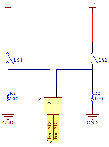
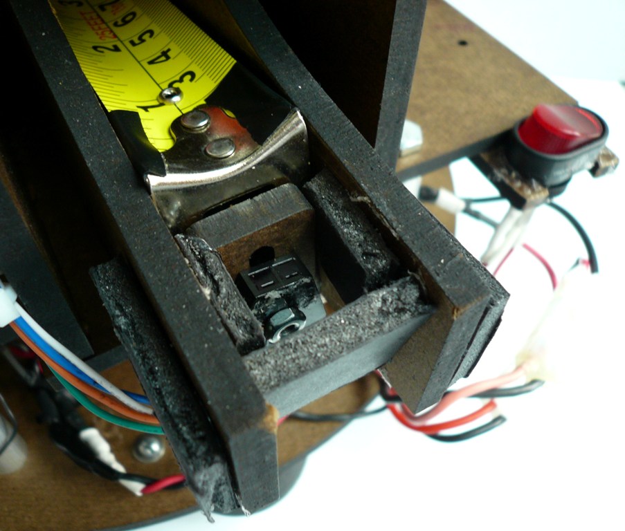
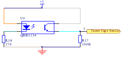
The orientation and extension of the turret were controlled by just 3 sensors. Two limit switches at either extreme range of motion prevented the turret from rotating endlessly and are used to aim at goal 3, depending on which side of the playing field the bot is on. A tape sensor is used in conjunction with calibrated marks on the underside of the tape measure ramp to control the distance that the tape measure extends.
Circuit
The tape sensor circuit is similar to that above, but with slightly different resistor values and software, rather than hardware hysteresis.
The limit switch circuits are extremely simple, and are shown together below.