


Jump To:
HELM: Overview Power ComBoard Control Inputs Display
BOAT: Overview Power ComBoard Actuator Control
----------------------------------------------------------------------------------------------------------------------------------------------------------------


----------------------------------------------------------------------------------------------------------------------------------------------------------------
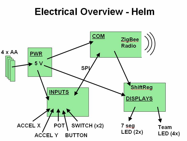
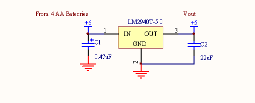
Helm Power
Power for the helm is
provided by 4 AA batteries, with an optional mount for an additional 4 in
parallel to increase available power if necessary to meet the 8 hour runtime
requirement.
|
Helm Power Consumption Estimate |
|
|
|
|
|
|
Part |
|
current |
%of
time on |
total
(mA) |
|
|
Shift
register |
80uA |
0.08 |
1 |
0.08 |
|
|
BCD to
7-seg decoder |
103mA all
on |
103 |
0.7 |
72.1 |
|
|
9 LEDs in 7- seg displays 5V, 510
Ohms |
49.5mA |
49.5 |
0.7 |
34.65 |
|
|
Jumbo Red
LED 5V, 510 Ohms |
6.28mA |
6.28 |
0.45 |
2.826 |
|
|
Jumbo
blue LED 5V, 510 Ohms |
2.75mA |
2.75 |
0.45 |
1.2375 |
|
|
Jumbo Red
LED 5V, 390 Ohms |
8.21 mA |
8.21 |
0.45 |
3.6945 |
|
|
Jumbo
blue LED 5V, 390 Ohms |
3.6 mA |
3.6 |
0.45 |
1.62 |
|
|
10K pot,
5v |
.5mA |
0.5 |
1 |
0.5 |
|
|
3 10K
resistors with switches |
1.5mA |
1.5 |
0.3 |
0.45 |
|
|
1 PIC 5v,
10Mhz osc |
1.3mA |
1.3 |
1 |
1.3 |
|
|
LM6144 |
1300uA |
1.3 |
1 |
1.3 |
|
|
Accelerometer |
1.5mA |
1.5 |
1 |
1.5 |
|
|
5x 2n7000 |
5uA |
0.005 |
1 |
0.005 |
|
|
PIC on
3.3v, 10 Mhz |
700ua |
0.7 |
1 |
0.7 |
|
|
Zigbee module (TX- RX and standby less) |
270mA |
270 |
0.1 |
27 |
|
|
|
|
|
mA |
148.963 |
|
|
|
8hrs uses |
1192 |
mA*h |
||
Given two sets of 4 AAs in parallel, we expect at least 1500 mA*h using quality batteries. Thus we should be able to make the 8 hour runtime minimum.
----------------------------------------------------------------------------------------------------------------------------------------------------------------


----------------------------------------------------------------------------------------------------------------------------------------------------------------
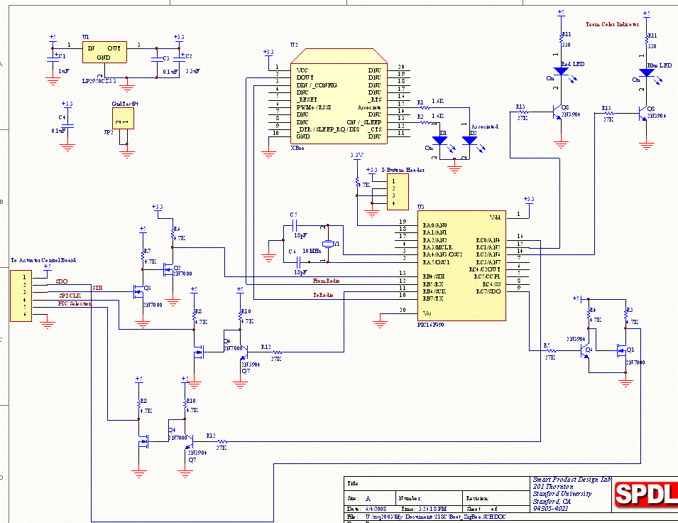
Helm Communications
Board
The helm’s game state machine is running on the PIC on this board. It handles the signal going to and received from the ZigBee chip through SPI. The signal coming from the Helm Control Inputs Circuit is read through SPI, because two bytes are needed to get all control signals (direction, driving power, pump power, special function), RC0 is used as General Input see what kind of data the byte received indicates.
RC3 and RC4 are used as data & clock output to the shift register on the Helm Display Board, to show our team number on 7-seg display and our team color on two LEDs.
Also, the helm I-buttom reading and goal color indication LEDs are controlled on this board.
Both the ZigBee and PIC on this board use 3.3V logic, thus conversion circuit is needed when communication to other boards, which use 5V logic.

----------------------------------------------------------------------------------------------------------------------------------------------------------------


----------------------------------------------------------------------------------------------------------------------------------------------------------------
Helm
Control Inputs
The control input PIC takes
in data from a 2 axis accelerometer for speed and direction, a potentiometer
for pump strength, a button for water fire, and two limit switches to control
turret motion direction (the special action bits in the communication
protocol). The Input PIC continually
updates the state of the inputs, assembles them into bytes according to the
communication protocol, and passes them to the communication PIC via SSP whenever
they are requested.
Helm
Control Inputs Circuit
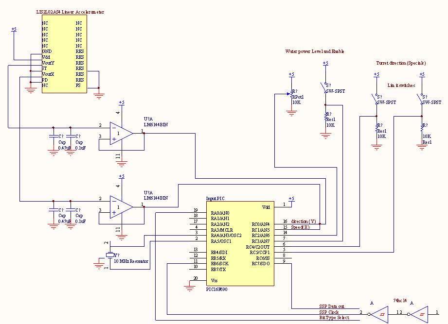
The accelerometer outputs an
analog value centered on 2.5V to indicate movement one way or the other in each
of two axes. The output needs to be
buffered so that the output impedance is low enough for the PIC to read it, and
must be filtered (capacitors to ground) to eliminate the high frequency spikes
(eliminate sensitivity to hard acceleration and leave only sensitivity to tilt
of accelerometer). The rest of the
inputs are simple, a 10K potentiometer, a button, and two of the roller type
limit switches, all connected to 10k resistors to provide good signal without
consuming too much power.
----------------------------------------------------------------------------------------------------------------------------------------------------------------


----------------------------------------------------------------------------------------------------------------------------------------------------------------
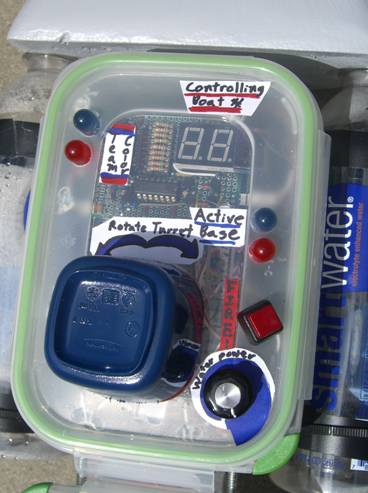
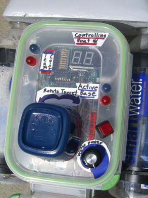
Helm
Displays
To communicate information to
the user, the helm incorporates two 7-segment LED displays for indicating the
boat under control and two pairs of large LEDS to indicate the current active
base and the team affiliation.
In order to save output pins
on the communications PIC, the craft number display and team affiliation LEDs are controlled by a shift register and BCD to
7-segment decoder.
Helm
Display Circuits
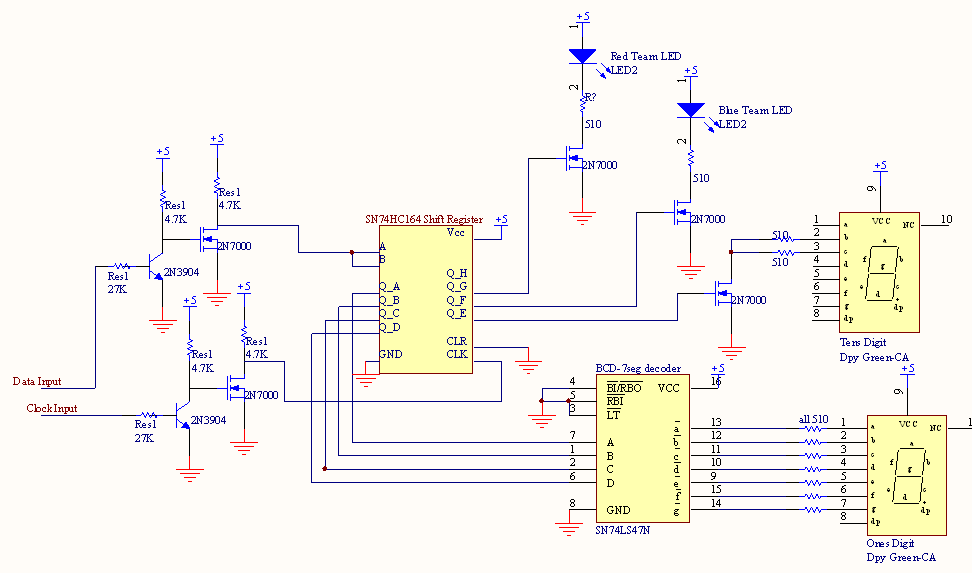
The shift register allows
the use of two output pins to shift out 8 bit values to the pins of the shift register. The lower nibble of the shift register output
is a binary representation of the ones digit of the craft number, which the BCD
to 7-segment decoder converts to digits on the display. Bit 4 of the shifted byte controls an
N-Channel MOSFET that controls the tens place of the craft number. Because the craft number is always less than
12, only two of the LEDs are connected. Bytes 5 and 6 control the team affiliation LEDs.
----------------------------------------------------------------------------------------------------------------------------------------------------------------


----------------------------------------------------------------------------------------------------------------------------------------------------------------
Boat
Overview
----------------------------------------------------------------------------------------------------------------------------------------------------------------

----------------------------------------------------------------------------------------------------------------------------------------------------------------
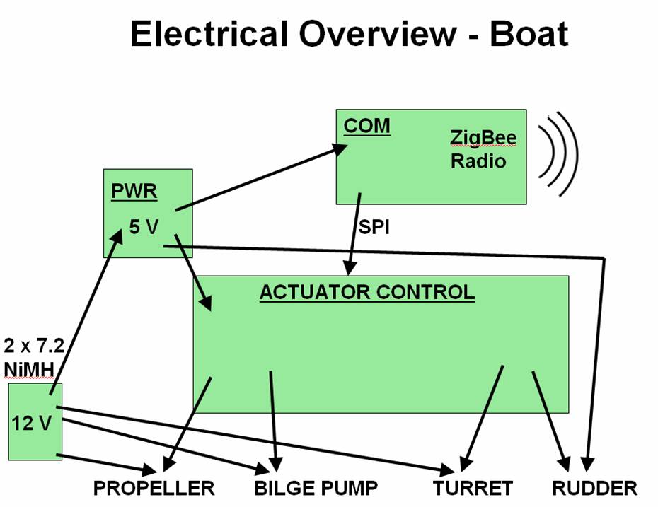
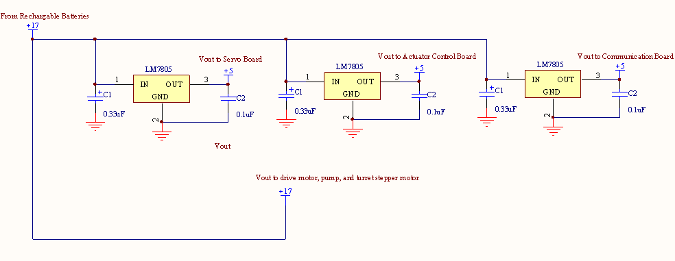
Boat Power
The power for the watercraft
is provided by a pair of rechargeable 1500mAh NiCAD
batteries, which actually provide a total of ~17V when fully charged. Unregulated battery power is provided to the
drive motor, pump, and turret stepper motor (controlled by MOSFETs
and H-Bridges). The rest of the power is
regulated to 5V, through three separate LM7805 1A regulators (One for the
servo, one for the actuator control board, and one for the communication
board).
----------------------------------------------------------------------------------------------------------------------------------------------------------------


----------------------------------------------------------------------------------------------------------------------------------------------------------------
Boat Communications
Board
The boat’s game state machine is running The PIC on this board. It handles the signal going to and received from the ZigBee chip through SPI, interprets the command received, and send out control signals to the actuator control board through SPI, since there are two PICs to talk to on the actuator control board, RC0 is used as General Output to select which PIC to talk to.
Also, the boat I-buttom reading and team color indication LEDs are controlled on this board.
Both the ZigBee and PIC on this board use 3.3V logic, thus conversion circuit is needed when communication to other boards, which use 5V logic.
----------------------------------------------------------------------------------------------------------------------------------------------------------------
----------------------------------------------------------------------------------------------------------------------------------------------------------------
Actuator
Controls
All four actuators on the watercraft are controlled remotely by the user interface on the helm. These inputs are communicated over radio to the Communications PIC onboard the watercraft. This microprocessor handles the input data and converts it into commands for the actuator control board. The data is then sent by SPI to one of two actuator controllers on the craft – the propeller/pump controller or the rudder/turret controller. Each of these is a PIC16F690. This communication is effectively one-way, with data coming from the Communications PIC and going out to either of the two controller PICs. The Com PIC’s SPI data input line is disconnected, and therefore no data returns from the Actuator Control Board to the Communications Board. Thus, we decided to simply use a single data and clock line, split to each PIC, and then use the Slave Select feature to disable or enable the proper PIC.
Two PICs were chosen in order to most simply control the actuators. Each PIC has only a single hardware PWM channel, so we decided to use a software-driven PWM for each the propeller, the pump, and the servo.
Actuator
Control Circuits
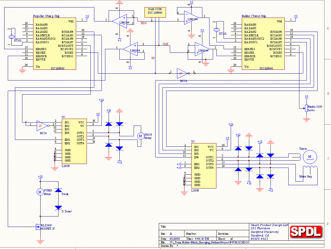
We encountered many difficulties in correctly receiving data from the Com PIC. Eventually, we traced this problem down to the interactions between two slave PICs reading the same input line. For this reason, we used a rail-to-rail op-amp to buffer the clock and data in lines to each actuator controller. This solved our problems with inconsistent readings. Beyond that, all implementations for the actuators were fairly standard and will be discussed quickly, one at a time.
Futaba 1300 Servo Motor: This servo uses the width of a pulse HI to set its angle. The input line is for logic only and does not draw enough current to require a driver beyond the sourcing capabilities of the PIC output pin. Software safeties were put in place to prevent overly short or extended pulses that could jam the servo at either of its limits. The servo draws approximately 1A directly from its own 5V regulator on the craft power board.
Propeller Motor: This DC motor has a stall current of just over 1 A, as determined by quick lab testing. Therefore, we decided to use the L293B H-Bridge which can run at 1 A continuously and 2 A peak. To keep from needing to switch multiple lines quickly during PWM, the direction is tied to the IN1 and IN2, while the PWM is tied to the ENABLE. Thus only a single line would switch at high frequency. Protection diodes were used to keep Back EMF from damaging the driver chip.
Bilge Pump: The bilge pump we used was rated to run at 3 A. For this reason, we needed a power MOSFET like the IRLZ34N. This allowed minimal power dissipation because of a low Rds,on. Further, we did not need directional control, so the use of a high-power H-Bridge was deemed unnecessary. Again, a pair of protection diodes circumvented large spikes in voltage due to Back EMF.
Stepper Motor: The stepper was run using 4 output lines and full step mode. The 20 ohm coil resistance running at 12 V gives about 600 mA current, which is well within the limits of the L293B driver chip. To prevent the stepper from overheating, a software timer would de-energize the coils after about 2 seconds without a change in position.