|
|
E128
|
|
C32
|
|
Port
|
Connect
|
Port
|
Connect
|
|
PU0
|
Tape-Outside Left
|
PE0
|
|
|
PU1
|
Tape-Inside Left
|
PE1
|
|
|
PU2
|
Tape-Inside Right
|
PT0
|
Drive Motor PWM-Left
|
|
PU3
|
Tape-Outside Right
|
PT1
|
Drive Motor PWM-Right
|
|
PU4
|
|
PT2
|
Latch Actuator
|
|
PU5
|
|
PT3
|
Switch Presser
|
|
PU6
|
|
PT4
|
Ball Gate Actuator
|
|
PU7
|
|
PT5
|
|
|
PT0
|
Beacon-Left Eye
|
|
|
|
PT1
|
Beacon-Left Eye
|
PT6
|
|
|
PT2
|
Beacon-Right Eye
|
PT7
|
|
|
PT3
|
Beacon-Right Eye
|
PAD0
|
Drive Motor Direction-Right
|
|
PT4
|
Flash Detector
|
PAD1
|
Drive Motor Direction-Left
|
|
PT5
|
|
PAD2
|
Latch Actuator Direction (if needed)
|
|
PT6
|
|
PAD3
|
Switch Presser Direction (if needed)
|
|
PT7
|
|
PAD4
|
Ball Gate Actuator Direction (if needed)
|
|
PE0
|
|
PAD5
|
|
|
PE1
|
|
PAD6
|
|
|
PE7
|
|
PAD7
|
|
|
PAD0
|
Beacon-Left Eye Analog
|
PM0
|
|
|
PAD1
|
Beacon-Right Eye Analog
|
PM1
|
|
|
PAD2
|
|
PM2
|
SPI-MISO
|
|
PAD3
|
|
PM3
|
SPI-SS
|
|
PAD4
|
Rear Tape-Left
|
PM4
|
SPI-MOSI
|
|
PAD5
|
Rear Tape-Middle
|
PM5
|
SPI-SCK
|
|
PAD6
|
Rear Tape-Right
|
|
|
|
PAD7
|
|
|
|
|
PP0
|
Debug LED
|
|
|
|
PP1
|
Debug LED
|
|
|
|
PP2
|
Debug LED
|
|
|
|
PP3
|
Debug LED
|
|
|
|
PP4
|
Debug LED
|
|
|
|
PP5
|
Debug LED
|
|
|
|
PS2
|
|
|
|
|
PS3
|
|
|
|
|
PS4
|
SPI-MISO
|
|
|
|
PS5
|
SPI-MOSI
|
|
|
|
PS6
|
SPI-SCK
|
|
|
|
PS7
|
SPI-SS
|
|
|
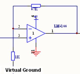
The beacon sensing circuit is comprised of five stages: a
transresistive circuit, a high-pass filter, a non-inverting amplifier, a low
pass filter, and finally a Schmitt trigger. The output of the comparator is
sent to Ports T0-3 on the C32, where rising and falling edges on each of the
two beacon sensors are logged to calculate duty cycles in software.
Virtual Ground
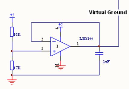
The virtual ground was set near 4.1 V (actually at 4 V
from measurement) using a voltage divider.
We chose this value to get maximal resolution in signal strength prior
to railing the op-amp.
Vout
= 5 V(1-(10/57))
= 4.122 V
and a buffered output to lock in this voltage.
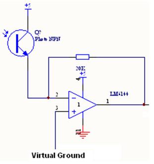
Stage 1: Transresistive Circuit
A LTR-3208E phototransistor (PT) runs current dependent on
the intensity of IR light incident on it. This current flows from the PT to Virtual
ground, set at about 4 V, so that the output voltage is a measure of the
current from the PT. We used the LM6144 so that the op-amp will go all the
way down to ground before railing. The 20K resistor was chosen by trial and
error to achieve a visible signal, but to avoid railing at this stage.
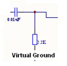
Stage 2: High-Pass Filter
A high-pass filter is used to get rid of low frequency
signals including ambient light. The time constant was chosen for a cutoff
frequency:
R
= 2.2K, C = .01 nF
Fc = 1/ (2 pi*R*C)
=
7 MHz
This high cutoff frequency correctly attenuates any slow
signals, while also destroying the square waves from the Stage 1. Instead,
the rising and falling edges become spikes up and down from the virtual
ground.
Stage 3: Non-Inverting Amplifier
The rail-to-rail opamp was used to amplify the small
signal from the RC filter. Using R2 = 47 K and R1 = 1K as shown, the
amplification desired is:
Gain = dVout/dVin
=
1 + (47K / 1K)
=
48
This step is meant to vastly increase the magnitude of the
signal, around the virtual ground. Note that the input goes into the + terminal
and will not need a separate buffer. Gain was chosen by trial and error
considering the desired output V(pk-pk) at certain distances and duty cycles.
Choosing the 6144 was important as we expected frequent railing of the output
at either 0V or 5V.
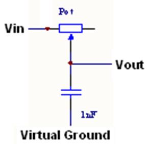
Stage 4: Low-Pass Filter
Next we included a low-pass filter to get rid of a lot of
the noise we were seeing from out motors turning. This noise was for the most
part much higher frequency than the 1.25 kHz PWM frequency of the beacons. We
used a potentiometer to tune the cutoff frequency in a range, taking care to
maintain the approximate 1.25 kHz square wave from Stage 3.
R =
1-10K C = 1 nF
Fc = 1/(2 pi * R *C)
FcMin = 15.9 kHz
FcMax=
159 kHz
Stage 5: Schmitt Trigger
A Schmitt trigger was designed to include a small
hysteresis band near the virtual ground value. We did not need a pull-up resistor
because the comparator is not open collector. We also verified that adding a
pull-up did not change performance at all.
These resistors were chosen to get a fairly narrow hysteresis band:
V+ (HI) = VirtualGround + (1K / 101K)*(5 V – VirtualGround)
= 4.01 V
V+(LO) = VirtualGround - (1K / 101K)*(VirtualGround)
= 3.96 V
This gave the desired results; the approximate square wave
from stage 4 was cleaned up and spread from ground to logic HI.
Low Pass Filter (Analog Input)
In addition to the five stage digital filter, we also
included a low pass filter after the transresistive stage that fed directly
into the analog inputs. The low pass
filter was designed to smooth out the square wave signal (thus losing all
duty cycle information) but it would give us the relative signal strength
between left and right sensors. This
analog signal was used to home in towards a beacon, the results of which can be
seen in the Sensor Strategies section.
The robot used seven tape sensors total. Four sensors were mounted on the frontbot,
to allow it to line follow autonomously.
Because we wanted the E128 to do all of the sensing, and since we used
two A/D ports for beacon sensing, not all seven tape sensors could be read
A/D. The three tape sensors in the
back were read A/D as in Lab 8, but the four in the front were fed through a
comparator and then read as a digital input.
The comparators could be tuned with a trimpot, which let us adjust the
cutoff voltage on the fly.
Unfortunately, for whatever reason, despite constant tuning, the tape
sensors were still finicky and either read false positives or sometimes
missed the tape entirely.
The tape sensors include an IR emitter and detector in a
single package. To wire up the emitter, we put a 120 ohm resistor to ground
to limit current. The IR LEDs are rated for up to 50 mA, and we expect:
I LED
= (5 V - V LED) / 120 ohm = (5 – 1.6)/120 = 28.33 mA
Thus this should be a good choice.
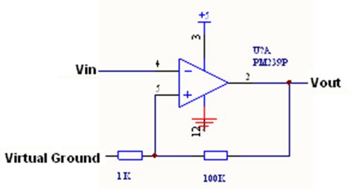
The detector is read through a transresistive circuit. The
+ terminal on the LM324N is set to ~3V using a potentiometer. Through trial
and error we found that a 1 K resistor from this 3V to the opamp output was a
good amplification of the PT signal. The voltage out demonstrates the amount
of IR light reflected back to the detector. We hooked this voltage to a comparator
on the front sensors and directly in to the A/D for the rear sensors.
Front Tape Circuit
Rear Tape Circuit
Latch and Switch Motors
The motor driver for the latch runs off of a simple
H-bridge setup using the L293B chip.
The one modification is the addition of two tactile switches with
pull-down resistors. These tactile
switches allow us to manually drive the latch motor in and out—to setup and
debug the robot—while allowing the C32 to drive the motor in one direction
(to disconnect the two robot halves).
The motor driver for the switch motor, also shown below,
is run bidirectionally through another a H-bridge on the same L293B chip.
Drive Motors
We were required to use two supplied Maxon motors in order
to move our robot around the playing field. We used the supplied motor driver
boards, which use a high current TLE5206 H-Bridge to switch the high current
required for this low resistance motor. To make sure we understood how this
driver board works, we took a usage quiz (shown below) and learned how to
design with this board. For instance, we used a relatively low PWM frequency
of about 1 kHz in order to minimize error in duty cycle from turn on/off
times. Furthermore, we found we needed only a single PWM line for
bi-directional control. The other direction line was tied to a digital output
from the C32. With the C32 Digital Output HI, we would pulse the PWM LO to
make the motor drive, while with the Digital Output LO, we would pulse the
PWM HI to make the motor run. Thus, the “sense” of the duty cycle had to be
reversed when direction was reversed. Other than these design points, the
electrical design for the driver board was handed to us with appropriate
capacitors to hold the power rails steady. Lastly, we did not need to
regulate the motor voltage as our algorithms were not very speed dependent,
so long as both motors were affected simultaneously.
TLE-5206 Usage Quiz
1) What is the minimum battery voltage necessary
to guarantee that the TLE-5206 will
start up and drive a motor?
Vuv on, max = 6 V
2) As the battery voltage falls, at what voltage
will the TLE-5206 shut down? What is the
parameter called in the data sheet?
It will shut down at a maximum of 5.6 V
and a minimum of 3.5 V (Vuv off)
3) Given a 10% duty cycle drive signal, what is
the maximum PWM frequency that will
result in less that 2% difference between the
drive signal high time and the voltage
applied to the motor? Use worst case
specifications.
We are then switching between the SOURCE
ON and SOURCE OFF conditions. We do not care about delay, because the phase
of the PWM is not important. Rather we care about switching times for the
output. For worst case in difference of time for output voltage, I’ll use the
ON max and the OFF min for greatest difference:
t_on H max = 30 us
t_off H min = 0 us
à
max 30 us difference between drive high time and motor voltage high. 30 us =
2%*10%*(1/PWMfreq) à
PWMfreq = 66.7 Hz
4) What is maximum battery voltage that you
could use with the TLE-5206?
Vs max = 40 V and
Vin1,2(logic) = 7 V
5) What is the minimum number of PWM lines
necessary to do sign-magnitude based bidirectional
control of a motor using the TLE-5206? (hint:
the data sheet is wrong)
A minimum of 1 PWM line for bidirectional
control.
6) Explain how you would use the minimum number
of lines to both adjust the speed and
direction of the motor.
One input would be a direction
control while the other would control duty cycle. However, in one direction
the duty would be measured low time and the other direction would be measured
high time. For instance, Duty_CW = 100 – Duty_CCW
7) What is the minimum voltage level necessary
to produce a logical high on the control
inputs to the TLE-5206?
The minimum logical high is a
max of 2.8 V (Vinh)
8) What is the minimum input current that your
control outputs should be prepared to
source or sink in order to be sure of being able
to drive the control inputs on the TLE-
5206?
The outputs
must be able to sink 10 uA (Iinl) and source 2 uA (Iinh)
A phototransistor was used to detect the flash, which has
some IR light in it. Before the flash, almost no current flows across the PT
and the low side is pulled down by a 510 ohm resistor. This value lets the
low side voltage be fairly low: using Iceo,dark
= 100 nA then Vlowside ~ 100 nA * 510 ohm = 51 uV.
When the flash goes off, much of the current flows to the
capacitor and charges it. Scoping it shows that the voltage goes well above
the threshold for logical HI on the C32. Then, after the flash, the charge
dissipates through the 10K resistor. The capacitor and resistor were chosen
for a relatively long fall time so the C32 could easily catch the high spike.
TRISE
= 2.2*R*C = 2.2 * (47 nF) * (10 Kohm) = 1.03 ms
|