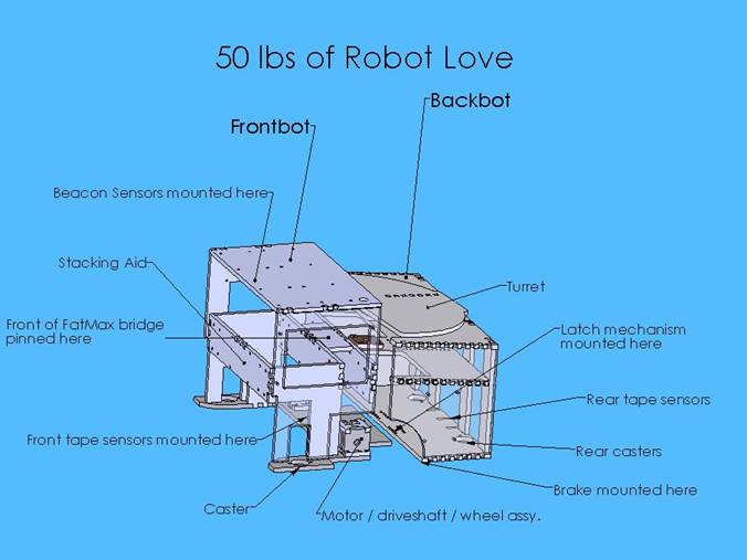
Frontbot Design
  We
recognized early on that space constraints were going to be a major factor in
our mechanical design. Since we
planned to fit our robot on top of Goal 3 and stack balls off of the ground,
there needed to be a 4x9x6 area of dead space at the front of our robot. Furthermore, this restriction also meant
that we could not place any tape sensors at the front of the robot, like we
had in Lab 8. To achieve line
following, we used four tape sensors aligned along the axis of the drive
motors. We divided the base 12x12x11.5
space into two equal sections, so the front half needed to fit in a
relatively small space, be able to drive and sense autonomously and envelop
Goal 3. A couple of iterations on
these constraints led to the design modeled to the left. The base of the robot extends 2 in. beyond
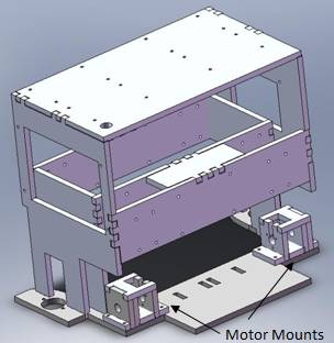
the 6 in. width to contain our latching mechanism, described below. The motor mounting blocks were made of acrylic
to provide a more firm attachment for the motors, which were coupled directly
to roller blade wheels using spider couplers.
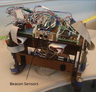
On the front half of the robot, all available space was used to mount
the C32 and E128 microcontrollers and circuitry for the four tape sensors,
beacon sensors, drive motors as well as power circuitry. Two batteries—one for the motors and one
for logic circuitry—were mounted using Velcro to the underside of the top
plate. Other features include a power
switch on the roof of the robot, two casters mounted at the front corners for
stability, a slight funnel at the front to help guide the robot over Goal 3
and two steel weights, also at the front, for added mass and stability when
extending the tape measure. We
recognized early on that space constraints were going to be a major factor in
our mechanical design. Since we
planned to fit our robot on top of Goal 3 and stack balls off of the ground,
there needed to be a 4x9x6 area of dead space at the front of our robot. Furthermore, this restriction also meant
that we could not place any tape sensors at the front of the robot, like we
had in Lab 8. To achieve line
following, we used four tape sensors aligned along the axis of the drive
motors. We divided the base 12x12x11.5
space into two equal sections, so the front half needed to fit in a
relatively small space, be able to drive and sense autonomously and envelop
Goal 3. A couple of iterations on
these constraints led to the design modeled to the left. The base of the robot extends 2 in. beyond
the 6 in. width to contain our latching mechanism, described below. The motor mounting blocks were made of acrylic
to provide a more firm attachment for the motors, which were coupled directly
to roller blade wheels using spider couplers.
On the front half of the robot, all available space was used to mount
the C32 and E128 microcontrollers and circuitry for the four tape sensors,
beacon sensors, drive motors as well as power circuitry. Two batteries—one for the motors and one
for logic circuitry—were mounted using Velcro to the underside of the top
plate. Other features include a power
switch on the roof of the robot, two casters mounted at the front corners for
stability, a slight funnel at the front to help guide the robot over Goal 3
and two steel weights, also at the front, for added mass and stability when
extending the tape measure.
Backbot Design
The rear half of the robot consisted of:
-
the latching mechanism, and the motor to drive
it
-
a brake and weights, such that the force of
the bridge being pulled out wouldn’t move or topple the backbot
-
a turret, such that the bridge could swivel
-
a funnel, such that the dispensed balls would
find their way onto the bridge
-
a bridge “tensioner,” such that the tape
measure maintained sufficient rigidity
-
tape sensors, to aid in the navigation prior
to separation.
-
A “whacker,” a DC motor with attached arm to
depress the ball dispenser button
While attached to the front half, the backbot was
essentially a chassis extension. The base level was even with that of the
front half of the bot, and contained two ball casters to allow the front half
to drive the back smoothly.
Latch
 Our overall strategy required that the
robot separate into two sections at the ball dispenser—the rear half would
stay at the dispenser and the front half—which has the drive mechanism—would move
to Goal 3. We needed to design a latch
mechanism that would allow the frontbot to push and pull the backbit to the
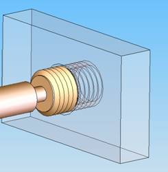
dispenser and then detach. The
mechanism we chose essentially a driven screw. An aluminum plate in the front half of the
bot was tapped for ½”-13 threads. Mounted directly to a DC gearmotor on the backbot
was a corresponding screw. By driving the motor such that it turned
clockwise, we could screw the two halves of the bot together. By driving it
in the opposite direction, the screw would force the front half (slightly)
forward and disengage. Our overall strategy required that the
robot separate into two sections at the ball dispenser—the rear half would
stay at the dispenser and the front half—which has the drive mechanism—would move
to Goal 3. We needed to design a latch
mechanism that would allow the frontbot to push and pull the backbit to the
dispenser and then detach. The
mechanism we chose essentially a driven screw. An aluminum plate in the front half of the
bot was tapped for ½”-13 threads. Mounted directly to a DC gearmotor on the backbot
was a corresponding screw. By driving the motor such that it turned
clockwise, we could screw the two halves of the bot together. By driving it
in the opposite direction, the screw would force the front half (slightly)
forward and disengage.
This type of latching scheme was chosen for several
reasons. It can be relied on to function despite significant loading in
almost every direction. A keyed latch of another sort would’ve been subject
to binding under the loads experienced by this robot. In addition, the latch
provided secure attachment from a single point. Finally, such a scheme was incredibly
simple to actuate.
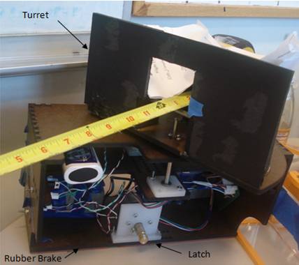
Brake
The backbot was actually constructed on a slant. While the
bottom level was indeed parallel to the ground (and to the base level of the
front bot), the upper two levels of the back bot were built at a 5° incline
(from the rear, the top surface of the bot angled 5° upward).
When the latch disengaged, the front half of the backbot
would fall those 5° onto a long rubber brake. A strip of gasket rubber 1/8”
thick and approximately ½” wide runs the width of backbot, and provides
friction once the weight of the backbot is resting on top of it. This prevents the frontbot from moving the
backbot as it pulls the FatMax tape measure forward.
Turret
The tape measure needed to swing smoothly and evenly to
prevent tipping on both frontbot and backbot sides. To allow this, we
constructed a turret, a level of the backbot that rotated with respect to the
lower levels.
The third level of the backbot had a flanged plain bearing
embedded in it. A precision ground
case-hardened steel shaft ran through this. To ensure alignment, a second
bearing was placed into an acrylic plate, which was then bolted onto the second
level of the backbot. At the top of
the shaft, a lasercut acrylic piece set screwed to the shaft. The turret
level then bolted on this set screw piece. The result was that the shaft spun
smoothly in the two bearings, carrying the turret level with it.
Bridge Tensioner
We noticed early on in experimenting with our tape measure
that a small upward force exerted at the base of the extended portion of the
tape made a great difference in the tape’s ability to resist torsion. We lasercut a series of masonite uprights
with holes at different heights. More precision ground shaft was put through
these holes, and with the variety of heights available, we were able to tune
the tension on the tape.
|