| Introduction | Design Process |
Mechanical Hardware |
Electrical Hardware |
Software | Gems of Wisdom |
Pictures/ Video |
Links |
|
|
while (1) butt.kick(); | |||||||
|
Individual Components
Complete CircuitElectrical Bill of Materials |
IR Detectors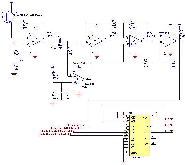 Virtual ground: is chosen at 2.5 V. It is used to the high pass filter, analog amplifier and comparator circuits. Transceiver: The larger R3 is, the larger the amplitude out of the phototransistor is but so is the response time of the transceiver. The value 10K and the reference voltage 2V are found experimentally to optimize the performance, ie. obtain a signal clean enough for the high frequency filter without reduce the performance at close range. Comparator circuit: Simple calculation gives us V+= 
V-=2.5-2.5*(10K/100K)=2.25V By experiment, these thresholds are enough to give a clean signal event at the longest range. Multiplexer: We use a multiplexer to physically choose which pair of IR Detectors to be used by the robot (front or side). This way the same code for front IRs can be used again for side IRs, only by writing 0 or 1 to PTT3 (see IR.c). The logic table of the multiplexer is shown below, the robot uses its front “eyes” when PTT3 is LO and its side eyes when PTT3 is HI. 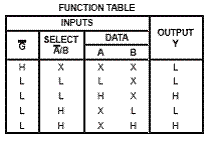
|