| Introduction | Design Process |
Mechanical Hardware |
Electrical Hardware |
Software | Gems of Wisdom |
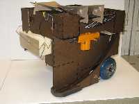
Pictures/ Video |
Links |
|
|
while (1) butt.kick(); | |||||||
|
Individual Components
Complete CircuitElectrical Bill of Materials |
Board 3 - Voltage Regulator, Auxiliary Motor Control Voltage Regulator: One voltage regulator is used to take as input 7.2V from the battery power supply and output 5V, which is used by all analog signal boards. The output is limited to 1A; however, the current required by the signal boards is well below this limit. Auxiliary Motor Control: Auxiliary motors are controlled using L293B H-bridges for bi-directional control. The maximum current output is 2A not continuous or 1A continuous. However, because these motors are used infrequently, 2A is a reasonable limit to expect. The lowest resistance motors used are the door-lock motors at approximately 3 ohms. However, there is a voltage drop at both transistors within the L293B of about 1.2 V. Driving the motors at 7.2 V, the current is calculated to be: (7.2V – 2.4V) / 3 ohms = 1.6 V, which is below the limit. |