| Introduction | Design Process |
Mechanical Hardware |
Electrical Hardware |
Software | Gems of Wisdom |
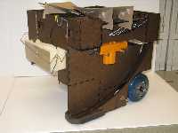
Pictures/ Video |
Links |
|
|
while (1) butt.kick(); | |||||||
|
Individual Components
Complete CircuitElectrical Bill of Materials |
Board 2 - Ball Sensor, Bump Sensor, and Amplifier Ball Sensor: The ball sensor consists of an IR emitter and two IR phototransistors, oriented such that one phototransistor is situated directly across from the emitter and detects IR intensity directly, and the other phototransistor is situated next to the emitter and detects IR intensity that is reflected off some surface. The phototransistor across from the emitter is used to detect whether the ball sorter is in its rest position and whether a black ball is blocking the IR emitter. The other phototransistor next to the emitter is used to detect IR reflected off a yellow ball. The phototransistor outputs go to A/D pins on the E128. Bump Sensors: The bump sensors are simply E128 pins tied to ground through a resistor and shorted to 5V when the button is closed. Non-inverting Amplifier: The non-inverting amplifier is used to amplify the tape sensor signal before it is read by the E128 A/D pin. The gain is calculated to be (1 + R2/R1) = 2.5. |