

|

|
Electronics - Lower Coin Sensors
|

|
|
|

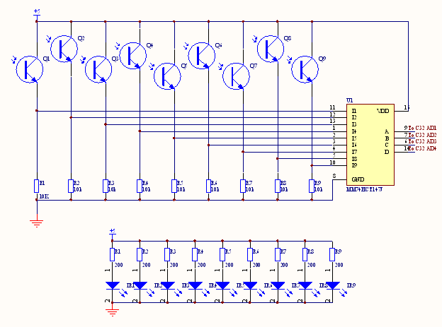
To detect the final slot the penny passes through on the Plinko board, nine pairs of infrared emitters (lower
circuit) and detectors (upper circuit) were used. In order to reduce the number
of C32 inputs necessary to monitor all of the slots, the signals from the emitter-detector pairs were encoded by an encoder
(MM74HCT147). Using an encoder allowed all slots to be monitored with only four input pins instead of nine.
Since a priority encoder was used, the detector output needs to be low when a coin
blocks the emitter-detector pairs. As can be seen in the truth table below, the output of the encoder reports which slot a coin was detected in by setting low the bits that correspond to that slot number in binary.
The IR LEDs used had a forward voltage drop of 1.1V. Based on this value, 200Ω resistors were chosen to
provide the LEDs with a 20mA current.
Since the output currents of the IR phototransistors (LTR3208) are highly
dependant on ambient conditions the functionality of the detector circuit was
verified experimentally. The low level output (coin present) was below the 0.8V
needed to set the encoder input low and the high level outpur (no coin present) were above the necessary 2.0V
for setting the encoder high.

|
|
|

|

|

|
|


