

|

|
Electronics - Timer LEDs
|

|
|
|

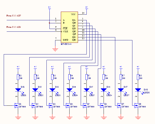
A shift register was used so that the eight LEDs of the timer could be controlled using two output pins on the C32 processor rather than eight.
Since the shift register logically ands the data inputs A and B, input B is always tied high. The reset input is also tied high since a low input resets the shift register. With this configuration, the data input (A) bit will be shifted into the Q outputs each time the clock is pulsed. If A is high, the LED will light, if A is low the LED will not light. Any
lighting pattern of the eight LEDs can be created by shifting in lit and unlit LEDs.
The output of the shift register connects to the gate of a 2N7000 MOSFET. When sufficient voltage
is applied, the MOSFET saturates and current flows through it to light the LEDs.
The yellow and red LEDs used had a forward voltage drop of 1.9V, the Green LEDs
had a voltage drop of 2.8V, and the 2N7000 MOSFET
has an RDS value of 5.3Ω. Based on these values, 200Ω resistors were chosen to
provide the red and yellow LEDs with a 16mA current and the green LEDs with 11mA when the MOSFET is saturated.
|
|
|

|

|

|
|


