 |
|---|
 |
 |
 |
 |
 |


We used an 8-bit shift register to control the LCD screen (which has many input pins) without using many of the C32 pins. The circuit schematic below shows how we were able to use just four pins of the C32 to control the LCD and provide another visual component of our game.
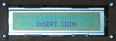 |
The LCD mounted in our game console |
Click here to see the software setup of the LCD
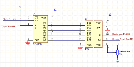 |
The outputs of the 8-bit shift register (left) is connected to the LCD (right) such that the LCD receives all information it needs. The software of the LCD allows us to connect the most significant bit on the LCD to the Q7 port of the shift register - hence the numbers match (e.g., Q0 -> DB0). In the shift register, values get progressively passed on when its clock pin signal is pulsed. When A is wired high, Q0 will take the value of B when the clock is pulsed and pass its previous value to Q1; Q1 passes its previous value to Q2, and so on. Once the clock has pulsed 8 times, the LCD's enable line can be pulsed and the instruction through the DB pins will be completed. |
Circuit schematic of our LCD and shift register setup |