 |
|---|
 |
 |
 |
 |
 |


To continue to conserve C32 pins, we wanted our motors to run on as few pins as possible. Thus we used a target motor circuit that would only need one C32 pin to set the speed of the motors through PWM. Another C32 pin is used to control the SWAG motor. Everything else about the motors is completely automated.
Click here to see the software setup of the motors
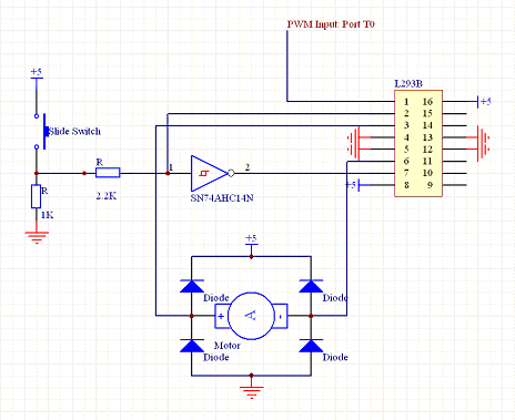 |
Our targets were to move left and right inside C-channel rails, and we wanted them to be able to change directions autonomously. We created a full H-bridge with a L293B push-pull driver to allow our motors to turn in both directions. In order to provide the proper direction control on the L293B chip, a HC14 Schmidtt trigger inverter is used to invert the signal from a slide switch mounted on our motors. The relation between inverter input and output signals are used by the push-pull driver to determine motor rotation direction. If the inverter input state changes due to the slide switch position, the polarity of the current across the motor also changes, which causes the motor rotation direction to change. The end result is that when the slide switch is pushed in one direction, the motor shaft turns in a certain direction, and when the switch slides in the other direction, the motor shaft will change rotation direction. One of these setups is used for each rail of moving targets. |
Circuit schematic of our target motor and slide switch system |