 |
|---|
 |
 |
 |
 |
 |


There are several miscellaneous smaller, yet key electrical components that were included in the game.
A 10K potentiometer with a user-friendly knob controls overall game difficulty. An C32 Analog to Digital port was connected to the wiper of the potentiometer, and the varying voltage levels were converted to a number that could be used as a PWM (Pulse Width Modulation) duty cycle to set the speed of the targets' left and right motion, as well as an indication to set other difficulty settings like cool-down time of the laser guns.
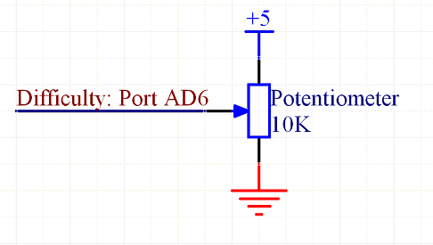 |
Circuit schematic of difficulty sensor |
For our game mode sensor, a ON-ON toggle switch was used with one ON wired to 5V and the other to 0V. A C32 port was configured to be an input, and reads high or low depending on the orientation of the switch.
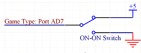 |
Circuit schematic of game mode switch |
The coin sensor circuit is shown below. Resistor values were calculated from the datasheet of the opto-interrupter (which is a combination of an IR-emitting diode and a phototransistor). Since the opto-interrupter signal is above the lowest voltage needed to be recognized as a high signal, no signal conditioning was needed.
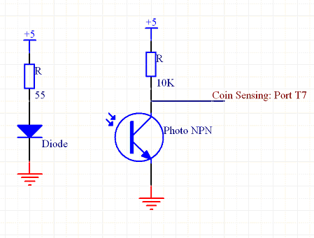 |
Circuit schematic of coin sensor |