 |
|---|
 |
 |
 |
 |
 |


Each of the eight alien foamcore target for our game has a red LED near the top of its head that when lit indicates which of the targets is active for the players to shoot at. Each target also has two photocells (photodiodes): one is positioned as a pupil in the left eye for Player 1 to shoot, and one is positioned as a pupil in the right eye for Player 2 to shoot. These photocells output an appreciably different voltage when sensing a red laser pointed at them than when sensing only ambient light. By monitoring the two photocell voltages of the target with a lit red LED, the game's software can determine when a target is hit and which player successfully earned the hit.
 |
One of our targets |
Click here to see the software setup of the Targets
Here is the circuit diagram of our target LEDs and photocells. In order to conserve pins on our C32, we used a MUX (top schematic) for each player's set of photocells for all targets and a decoder (bottom schematic) for our target LEDs. Varying the HI/LO signal combination on three C32 Analog/Digital ports determines which of the targets is active. The MUX A, B, C inputs are each connected to one of these A/D ports, and the signal combination of these inputs determines which one of the X0-X7 MUX input ports is connected to the X output port. This allows the voltage level of the photocell at the selected X input to be transmitted to the X output port, which is then read by another C32 A/D port to be assessed in software. |
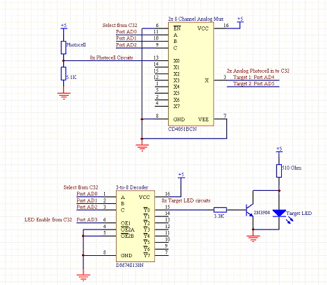 |
Circuit schematic of target LEDs and photocells |
|
The three C32 A/D ports that determine which target is active are also connected to the decoder A,B,C inputs, and their signal combination determines which one of the Y0-Y7 outputs (which are synchronized in their pin numbers with the MUX's photocell X0-X7 inputs) is "on". The C32 controls one of the enable lines of the decoder (the others are wired to ground), so through the C32, the game software can control the HI/LO signal on the decoder's selected "on" Y output. Each Y output is wired to a transistor-LED setup configured such that an LED turns on when its signal from the Y output is HI, so when the selected "on" Y output is HI, the desired target is indicated active by a lit LED.